Radio frequency system, antenna switching method and client front-end equipment

A radio frequency system and antenna technology, which is applied in the field of customer front-end equipment and radio frequency systems, can solve the problems affecting the communication performance of the radio frequency system and the complexity of control logic, etc., to improve communication performance, reduce the number of switching stages, and control the response accurately and timely Effect

Active Publication Date: 2021-03-09
GUANGDONG OPPO MOBILE TELECOMM CORP LTD
View PDF24 Cites 6 Cited by
  • Summary
  • Abstract
  • Description
  • Claims
  • Application Information

AI Technical Summary

Problems solved by technology

However, in order to realize the multi-antenna switching technology, multi-level switches need to be added in the radio frequency system, the control logic is complex, and it will also affect the communication performance of the radio frequency system

Method used


Image

  • Radio frequency system, antenna switching method and client front-end equipment
  • Radio frequency system, antenna switching method and client front-end equipment
  • Radio frequency system, antenna switching method and client front-end equipment

Examples


Embodiment Construction

[0041] In order to make the purpose, technical solution and advantages of the present application clearer, the present application will be further described in detail below in conjunction with the accompanying drawings and embodiments. It should be understood that the specific embodiments described here are only used to explain the present application, and are not intended to limit the present application.

[0042] It can be understood that the terms "first", "second" and the like used in this application may be used to describe various elements herein, but these elements are not limited by these terms. These terms are only used to distinguish one element from another element. For example, a first receiving module could be termed a second receiving module, and, similarly, a second receiving module could be termed a first receiving module, without departing from the scope of the present application. Both the first receiving module and the second receiving module are receiving ...


PUM


Abstract

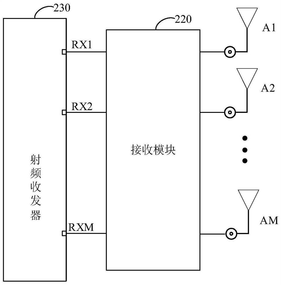
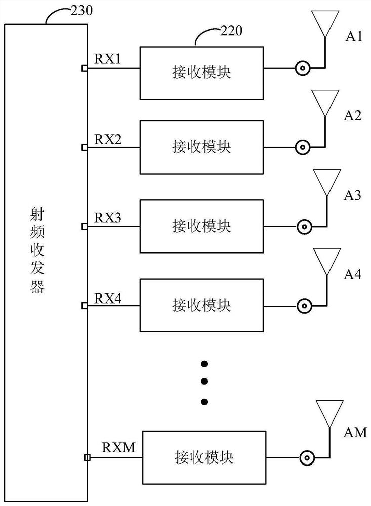
The invention relates to a radio frequency system, an antenna switching method and client front-end equipment, and the radio frequency system comprises a receiving module which is used for receiving and processing a radio frequency signal; M antennas, wherein each antenna of the M antennas and the receiving module are connected with the radio frequency transceiver, the M antennas are configured with M ports, and the M antennas are connected with the M ports in a one-to-one correspondence manner through the receiving module to form a preset receiving transmission path of each antenna; configuration information of a preset receiving transmission path is stored in the radio frequency transceiver, the radio frequency transceiver is further used for determining a target transceiving antenna group according to the radio frequency signal received by each port, the target transceiving antenna group comprises N antennas, wherein N is greater than or equal to 2 and less than M. According to theinvention, the insertion loss of a radio frequency front-end circuit in a radio frequency system can be reduced, the sensitivity performance is improved, and the communication performance of the radiofrequency system is further improved.

Description

technical field [0001] The present application relates to the technical field of antennas, in particular to a radio frequency system, an antenna switching method, and customer front-end equipment. Background technique [0002] Customer Premise Equipment (CPE) is a mobile signal access device used to receive mobile signals and forward them with wireless WIFI signals. It is also a device that converts high-speed signals, such as 4G or 5G signals, into WiFi signals. equipment. Generally, multiple antennas are configured in the customer's front-end equipment to support multi-antenna receiving switching. However, in order to realize the multi-antenna switching technology, it is necessary to add multi-level switches in the radio frequency system, the control logic of which is complex, and it will also affect the communication performance of the radio frequency system. Contents of the invention [0003] Embodiments of the present application provide a radio frequency system, an...

Claims


Application Information

Patent Timeline
Patent Type & Authority Applications(China)
IPC IPC(8): H04B1/401H04W88/10
CPCH04B1/401H04W88/10Y02D30/70
Inventor 周雷
Owner GUANGDONG OPPO MOBILE TELECOMM CORP LTD
Why Eureka
Try Eureka