Automated welding system for interchangeable welding heads

A technology of automatic welding and welding head, used in welding equipment, welding equipment, auxiliary welding equipment, etc.

Inactive Publication Date: 2021-03-09
ESAB AB
View PDF11 Cites 2 Cited by
  • Summary
  • Abstract
  • Description
  • Claims
  • Application Information

AI Technical Summary

Problems solved by technology

Then, on top of the cost of buying piles of automation systems, the end user has to store and maintain all of this equipment

Method used


Image

  • Automated welding system for interchangeable welding heads
  • Automated welding system for interchangeable welding heads
  • Automated welding system for interchangeable welding heads

Examples


Embodiment Construction

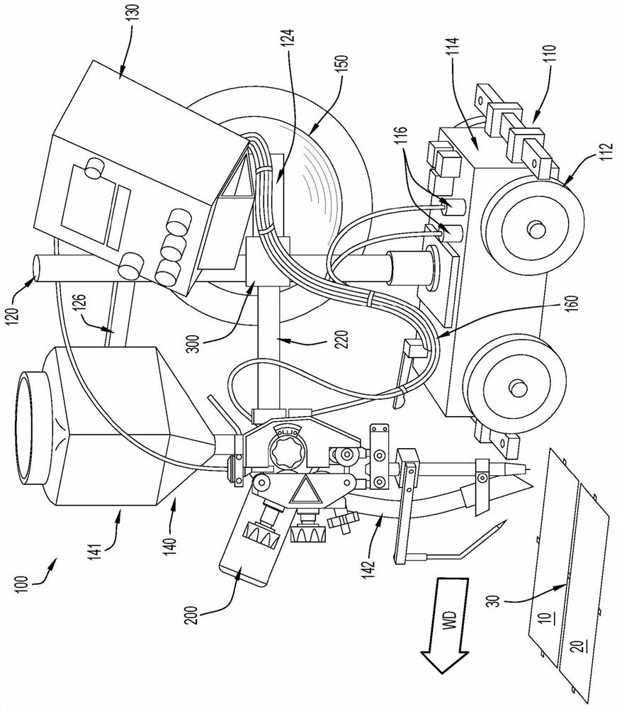
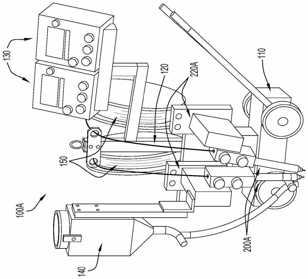
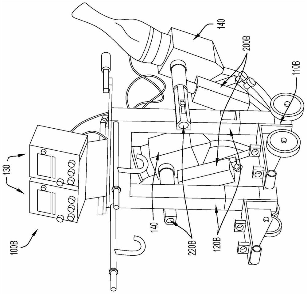
[0028]In general, this paper proposes a welding system capable of receiving and recognizing interchangeable welding tips. When an interchangeable welding head is identified, the system automatically configures itself to support welding operations with the identified welding head. That is, once one of the welding heads is electrically connected to a controller included on the welding device (e.g., tractor or column and boom), the controller can The cable associated with the welding head may have an identification resistor having a unique resistance value) to identify the welding head and configure features (e.g., activate or deactivate components such as the flux subsystem) and / or welding parameters accordingly (For example, limit the range of wire feed speed). Thus, an end user can use a single automation system for multiple types of welding operations, and the end user can quickly and easily switch between these welding operations. For example, an end user (i.e. operator) c...


PUM


Abstract

An automated welding system includes a support structure, a plurality of welding heads, and a controller. The plurality of welding heads are each removably, mechanically coupleable to the support structure. The controller is configured to control welding operations of the automated welding system based on an identity of a particular welding head of the plurality of welding heads that is mechanically coupled to the support structure and operably coupled to the controller.

Description

[0001] Cross References to Related Applications [0002] This application claims the benefit of U.S. Provisional Application No. 16 / 044,951, filed July 25, 2018, entitled "Automated Welding System for Interchangeable Welding Heads," the disclosure of which is incorporated herein by reference in its entirety. technical field [0003] The present disclosure relates to a welding system, and in particular, to an automated welding system configured to support a variety of interchangeable welding heads mountable on the system. Background technique [0004] Automated soldering is becoming more common due at least in part to the increased labor costs associated with achieving high quality manual soldering. Automated welding usually requires a large initial investment, but if the automated equipment is used frequently, the lower operating costs of automated welding often offset the higher cost of paying skilled welders over time. Automated systems come in a variety of form factors. ...

Claims


Application Information

Patent Timeline
Patent Type & Authority Applications(China)
IPC IPC(8): B23K9/095B23K37/02B23K3/03B23K9/10B23K10/00B23Q3/155
CPCB23K37/0241B23K9/095B23K9/10B23K10/006B23K3/033B23K28/02B23K11/318B23K37/0294B23K9/282B23K9/12B23Q3/155G05B19/16
Inventor M·斯维德隆德
Owner ESAB AB
Why Eureka
Try Eureka