Conveying device

A technology of conveying device and conveying equipment, which is applied to pump devices, components of pumping devices for elastic fluids, non-variable-capacity pumps, etc., can solve problems such as high component cost and achieve good adjustment effects

Active Publication Date: 2021-03-09
HANON SYST EFP DEUT GMBH
View PDF9 Cites 0 Cited by
  • Summary
  • Abstract
  • Description
  • Claims
  • Application Information

AI Technical Summary

Problems solved by technology

[0004] Valve distribution requires actuators with electronically actuated mechanisms and retaining mechanisms on components of the vehicle, which results in high component costs

Method used


Image

  • Conveying device
  • Conveying device
  • Conveying device

Examples


Embodiment Construction

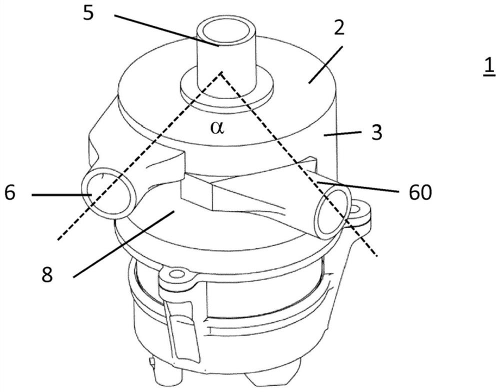
[0022] figure 1 An embodiment of a delivery device 1 according to the invention is shown. In this embodiment a water pump is involved, but the invention can also be applied to compressors.

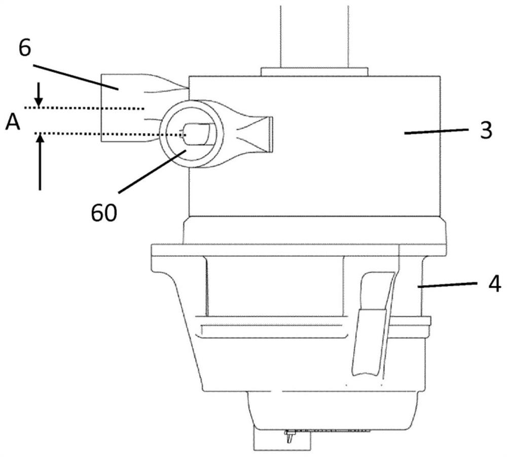
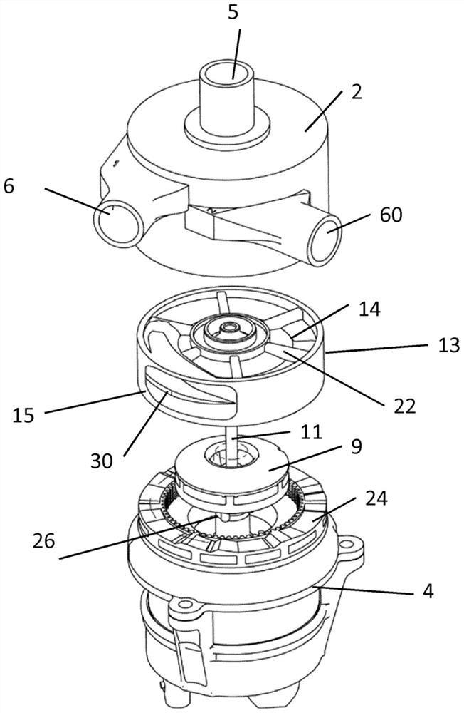
[0023] The conveyor device 1 has a housing 2 with a first housing part 3 as a housing pot and a second housing part 4 as a housing lower part for accommodating an electric motor. The second housing part 4 is attached to the first housing part 3 so that it can be closed and sealed.

[0024] The housing 2 has a suction opening 5 for sucking in a fluid, in this example eg water. The suction opening 5 is centered on the axis of rotation of the conveying device. Housing 2 also has two outflow openings 6 and 60 for the outflow of conveyed water or fluid. The housing 2 is substantially cylindrical and has a circumferential wall 8 . The outflow openings 6 are here arranged spaced apart from one another in the circumferential wall 8 . The two pump outlets are axially offset from each other so...


PUM


Abstract

The invention relates to a conveying device comprising an electric drive with a housing (2) having a suction opening (5) and a plurality of outlets (6, 60), and a conveying element (9) which is rotatably received in the housing (2) in order to produce a stream of fluid from the suction opening (5) to each outlet (6, 60), wherein the outlets (6, 60) are applied to the housing (2) in an at least axially interspaced manner.

Description

technical field [0001] The invention relates to a delivery device having a housing with a suction opening and a plurality of outlet openings, the delivery device having a delivery element which is rotatably accommodated in the housing , in order to establish a fluid flow from the suction opening to the corresponding outlet opening, wherein a ring element arranged radially outside the delivery element inside the housing is provided, by means of which ring element the fluid can be adjusted through the corresponding outlet opening flow. Background technique [0002] In vehicles there are various feed pumps for different fluids such as air, water, oil or mixtures thereof. [0003] One example is a cooling system with a water pump used to cool various electronic components of a vehicle. This is a hybrid or purely electric vehicle, since a vehicle with an internal combustion engine has no electrical components that must be cooled. To ensure the distribution of the coolant, valv...

Claims


Application Information

Patent Timeline
IPC IPC(8): F04D29/42F04D15/00
CPCF04D29/4293F04D15/0022F04D15/0027F04D29/486F04D29/628F04D29/426F04D13/06
Inventor 扬·欣里希斯托比亚斯·凯泽
Owner HANON SYST EFP DEUT GMBH
Why Eureka
Try Eureka