Spreading system and unmanned equipment

A technology of equipment and unmanned vehicles, which is applied in the directions of sowing, sowing planters, planter parts, etc., can solve the problem of uneven spreading of materials, and achieve the effect of improving the uniformity and the degree of uniformity.

Pending Publication Date: 2021-03-12
GUANGZHOU XAIRCRAFT TECH CO LTD
0 Cites 0 Cited by

AI-Extracted Technical Summary

Problems solved by technology

However, the spreading system provided by the related art s...

Method used

Fig. 10 is the exploded structural representation of cloud platform assembly 240 in the embodiment of the present invention; Further, please refer to Fig. 10, and cloud platform assembly 240 is connected with driver 231 by first support bar 233; No matter how many spreading components 230 are installed in the system 200, the same pan-tilt component 240 can be used to ensure the balance of all spreading components 230, so as to efficiently, reliably and uniformly spread materials.
Fig. 9 is the structural representation of sowing assembly 230 in the embodiment of the present invention Figure 2; Optionally, please refer to Figure 9, the spreading assembly 230 also includes a first housing 234, the first housing 234 is provided with a second housing chamber 2341, and the top of the second housing chamber 2341 has a first opening 2342, And the side wall of the second receiving chamber 2341 has a second opening 2343; the spreading plate 232 is arranged in the second receiving chamber 2341, the blanking opening 211 is opposite to the first opening 2342, and the second opening 2343 is away from the storage box body 212 is set; the material can drop from the first opening 2342 to the spreading plate 232 and can be spread out from the second opening 2343 . Further, the first housing 234 includes a bottom shell 2344 and a side shell 2345 which are connected to each other, the bottom shell 2344 is fixedly connected to the first support rod 233, the output shaft of the second motor passes through the bottom shell 2344 and is connected to the spreading disc 232, and the bottom shell 2344 is connected to the spreading disc 232. The shell 2344 is roughly semicircular, and the side shell 2345 is an arc-shaped side wall. The side shell 2345 is connected to the side of the bottom shell 2344 close to the storage box body 212. The side shell 2345 and the bottom shell 2344 together form a first opening. 2342 and the second accommodating cavity 2341 of the second opening 2343; so set, it can ensure that the beating plate 2322 can knock out the material without slipping from the side close to the storage box body 212, so as to improve the spreading efficiency and ensure the spreading quality .
Further, cloud platform assembly 240 is connected with driver 231, is used to control the balance of driver 231 and spreading disc 232; So is set, guarantees that spreading component 230 can also carry out the spreading of material evenly under the situation of turbulence Operation.
Further, sowing assembly 230 is arranged between chassis 111 and material storage box 210; Specifically, please refer to Fig. 3, form installation space 214 between material storage box body 212, transition box body 213 and chassis 111, sow The assembly 230 is arranged in the installation space 214; such arrangement can make the overall structure of the spreading system 200 compact, which is beneficial to miniaturization design.
It should be further explained that the conveying assembly 220 is arranged in the material storage box 210, and the sowing assembly 230 is arranged below the blanking opening 211, which is conducive to reducing the space occupied by the spreading system 200 as a whole, and realizes a compact structure. miniaturized design.
It should be further explained that the transition box body 213 of the present embodiment is provided with two blanking openings 211, and the two blanking openings 211 correspond to the two spreading assemblies 230 one by one, so that the spreading efficiency can be further ensured . Certainly, in other embodiments, the number of the discharge openings 211 may also be one, three, etc., which are not specifically limited here.
It should be further explained that, in order to ensure the compact structure of the spreading system 200, not only the screed shell 251 is arranged in the installation space 214, but also the third motor 253 that is arranged on the third housing 2513 is also located in the installation space 214 , so that the entire leveling device 250 is arranged in the installation space 214 , so that the compact structure of the spreading system 200 can be ensured.
Optionally, please refer to Fig. 11 and Fig. 12, the even material assembly 252 also includes the material guide plate 254 and the material retaining plate 255 arranged in the third housing 2513, the material guide plate 254 and the material retaining plate 255 are all It is arranged adjacent to the entrance 2511; wherein, the material guide plate 254 is located at the downstream of the rotation path of the screed wheel 2521 to ensure that the material can be in contact with the screed wheel 2521, thereby ensuring that the screed operation is carried out reliably; the baffle plate 255 is located at the screed wheel 2521 Upstream of the rotation path, to prevent too much material entering the third housing 2513 from the inlet 2511 from pressing down the leveling wheel 2521, that is, to prevent the leveling wheel 2521 from being blocked by the mate...

Abstract

The invention relates to the field of unmanned equipment, in particular to a spreading system and unmanned equipment. The spreading system comprises a material storage box, a conveying assembly and aspreading assembly, the material storage box is provided with a material falling opening, and the conveying assembly is arranged in the material storage box and used for conveying materials stored inthe material storage box upwards so that the materials conveyed by the conveying assembly can fall off from the material falling opening; and the spreading assembly is arranged below the material falling opening and is used for spreading materials falling from the material falling opening. According to the spreading system and the unmanned equipment, the uniformity degree of material spreading canbe improved.

Application Domain

Centrifugal wheel fertilisersSeed depositing seeder parts +1

Technology Topic

Aerospace engineeringMaterial storage +1

Image

  • Spreading system and unmanned equipment
  • Spreading system and unmanned equipment
  • Spreading system and unmanned equipment

Examples

  • Experimental program(1)

Example Embodiment

[0032] In order to make the objects, technical solutions, and advantages of the present invention more clearly, the technical solutions in the embodiments of the present invention will be described in contemplation in the embodiments of the present invention, and will be described, and the embodiments described in the embodiments of the present invention will be described. It is a part of the embodiments of the present invention, not all of the embodiments. Components of the embodiments of the present invention described and illustrated in the drawings herein can be arranged and designed in various configurations.
[0033] Thus, the following detailed description of the embodiments of the invention as provided in the drawings are not intended to limit the scope of the invention, but only the selected embodiments of the present invention are shown. Based on the embodiments of the present invention, those of ordinary skill in the art will belong to the scope of the present invention without all other embodiments obtained without creative labor.
[0034] It should be noted that similar reference numerals and letters represent the like items in the drawings below, and therefore, once one is defined in one bysertation, it is not necessary to further define and explain it in the following drawings.
[0035] In the description of the invention, it is to be noted that the orientation or positional relationship indicated by "upper", "lower", "vertical", "horizontal", "inside", "outside", etc. is based on the drawing. The orientation or positional relationship, or the orientation or positional relationship that is commonly placed in the use of the invention, is merely described in order to facilitate the description of the invention, rather than indicating or implying that the device or component must have a specific orientation. Structure and operation in a specific orientation, it is not understood to limit the limitation of the invention. Moreover, the terms "first", "second", "third", etc. are only used to distinguish description, and cannot be understood as instructions or implies relative importance.
[0036] Moreover, terms "horizontal", "vertical", and the like are not shown to be absolutely horizontally or overwhelmed, but can be slightly tilted. For example, "horizontal" is merely a more level in its direction relatively "vertical", and does not indicate that the structure must be completely level, but can be slightly tilted.
[0037] In the description of the present invention, it is also needed to be, unless otherwise expressly specified and defined, the term "set", "connection" should be used to understand, for example, may be a fixed connection, or a detachable connection, or Inserted; it can be a mechanical connection, or an electrical connection; may be directly connected, or indirectly connected by an intermediate medium, which may be in the interior of the two elements. The specific meaning of the above terms in the present invention will be appreciated to those skilled in the art.
[0038] This embodiment provides an unmanned device, which can refer to a unmanned vehicle, a drone or a boat, etc .; the following will be described in detail below.
[0039] Unmanned car, can be used to pigeons, fertilize, spray drugs, spread seeds, demonsticks, or sterilization, etc .; Of course, no car can also be used for delivery of goods in the express industry, or for fire fighting, etc. Not specific.
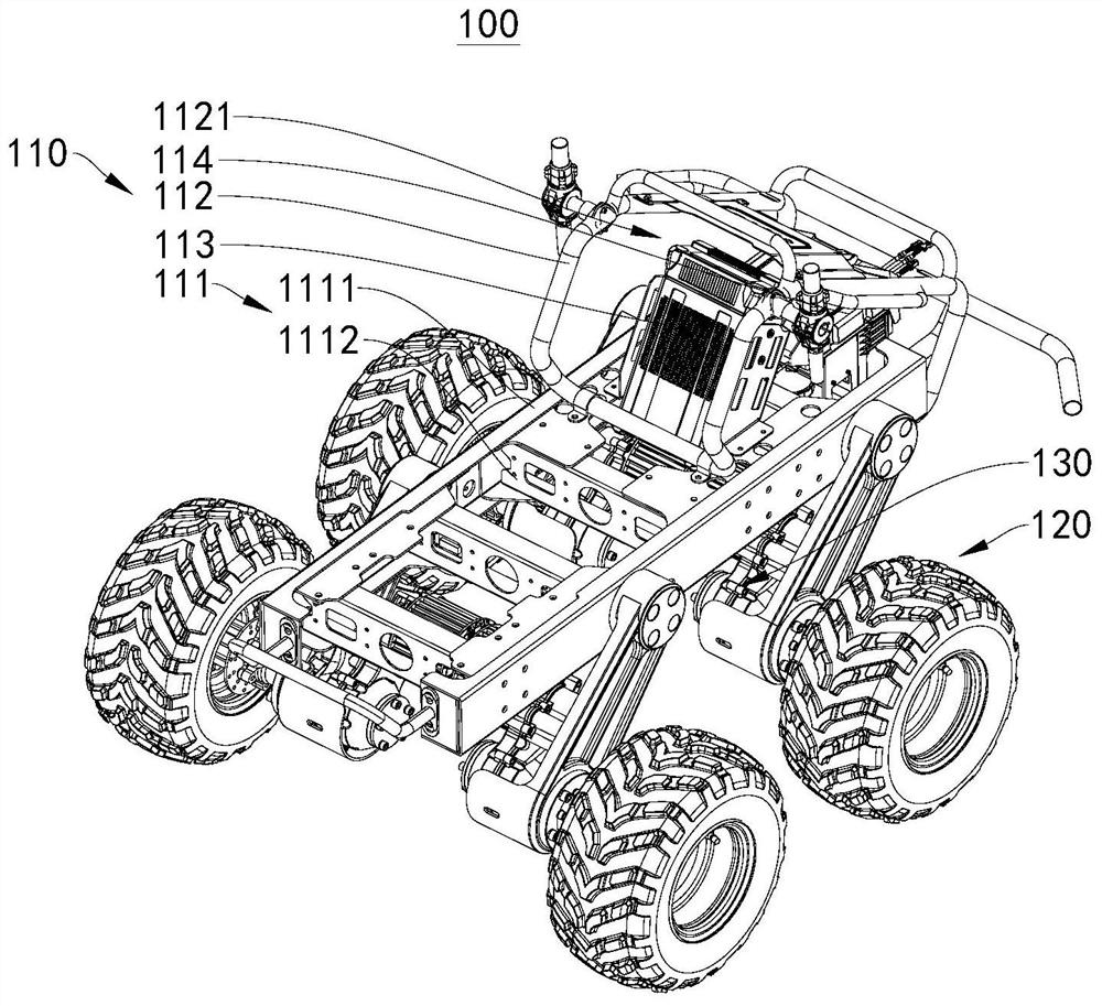
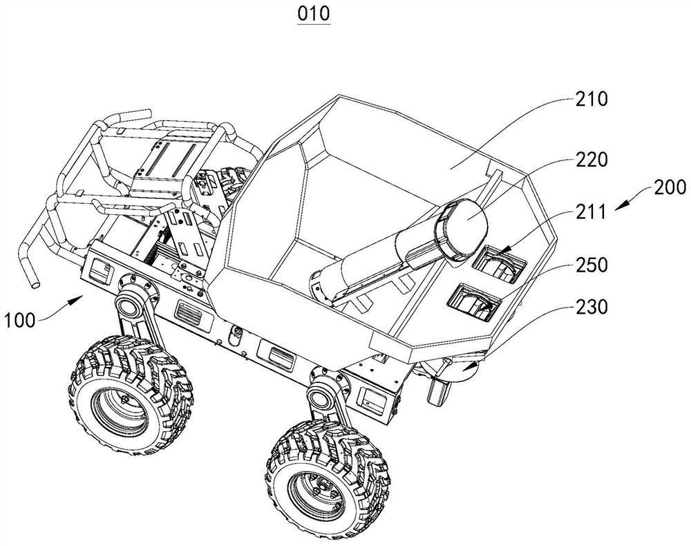
[0040] figure 1 A structural diagram of the unmanned car body in the embodiment of the present invention; figure 2 A structural diagram of the unmanned vehicle 010 in the first perspective of the present invention.
[0041] Please refer to figure 1 with figure 2 The unmanned equipment of the present embodiment includes an unmanned device, i.e., the unmanned car 010 includes an unmanned vehicle body 100; further, please refer to figure 1 The drone body 100 includes a vehicle body 110, a plurality of travel wheel assembly 120, and a plurality of drive assemblies 130, and the plurality of travel wheel assembly 120 are each provided in the body 110, and the plurality of drive assemblies 130 correspond to the plurality of travel wheel assemblies 120. To place, each drive assembly 130 is used to drive the corresponding walking wheel assembly 120 to move the body 110 to move.
[0042] It should be noted that the number of travel wheel assembly 120 can be selected as needed, and may be, for example, four sets of rectangular distribution walking wheel assembly 120, wherein the four sets of rows of wheel assembly 120 each two are distributed in the body 110. On both sides; of course, the number of travel wheel assembly 120 can also be three, five, etc., which are not specified herein. The structure and working principle of the walking wheel assembly 120 are similar to related technologies, and will not be described here.
[0043] Optionally, please refer to figure 1 The body 110 includes a chassis 111 and a bracket 112 disposed at the chassis 111, a power device 113, a control device 114, and a work device. Wherein, the chassis 111 includes two beams 1111 and a beam 1112 fixed between the two beams 1111; it is to be explained, the connection mode of the large beam 1111 and the beam 1112 can be welding, a fastener such as a bolt, or the like; two The number of beams 1112 connected between the beams 1111 can be one, two, three, etc., which are not specified herein. Alternatively, both the large beam 1111 and the beam 1112 can be selected from C-type steel or plate type steel, etc., which is not specified herein. It should be noted that the row of row wheel assembly 120 is fixed to the beam 1111.
[0044] The bracket 112 is fixed to the chassis 111; alternatively, the bracket 112 can be fixed to at least one of both the beam 1111 and the beam 1112, and the connection mode can be welded or fastened with a bolt or the like.
[0045] Further, please refer to figure 1 A first receiving chamber 1121 is formed between the bracket 112 and the chassis 111, the power device 113 and the control device 114 are located within the first receiving chamber 1121; wherein the power device 113 and the control device 114 are fixed to the chassis 111, both with the chassis. 111 The method of fixing the connection is similar to the related art, for example, the power device 113 is fixed to the fastener such as the laminate 1111 by a bolt. It should be noted that the specific structure of the bracket 112 is similar to the related art, and details are not described herein again.
[0046] Alternatively, the power device 113 is a battery for providing power to the unmanned vehicle 010, i.e., the work device, the drive assembly 130, and the control device 114 can be electrically connected to the power device 113 to supply power by the power device 113. The control device 114 can be connected to the work device and the travel wheel assembly 120 to control its operation, which is not limited to the specific type of the control device 114. It should be noted that the principles of the control device 114 are similar to those of the related technologies, and will not be described herein.
[0047] The operating equipment can be selected by the operator to choose from the different job types, thereby achieving job needs to meet a variety of agricultural operations to ensure operational effects and quality.
[0048] In this embodiment, the working device can be a broad-scale system for broadcasting the seeds, fertilizers, and the like. It should be noted that the propagation system provided in this embodiment can also be used in unmanned devices such as unparalleled or unknown, which is not specifically limited.
[0049] Of course, in other embodiments, the work equipment can also be a spray liquid system to water, defect and sterilize, defect, and sterilize, or the spray system can also be used for fire extinguishing systems. Picking device for picking operations, etc .; here is not specified.
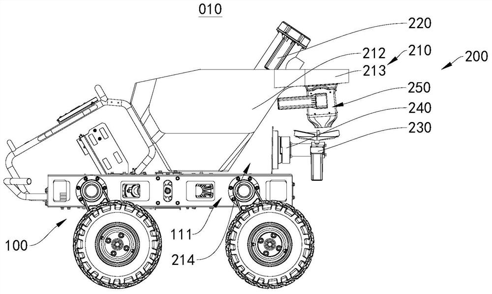
[0050] image 3 A structural diagram of the unmanned vehicle 010 in the second perspective of the present invention; please refer to figure 2 with image 3 The broadcast system 200 of the present embodiment includes a storage box 210, a conveying assembly 220, and a spreading assembly 230, and the storage box 210 is provided with a blasting port 211, and the conveying assembly 220 is disposed in the storage box 210 for use the storage tank. The material stored in the 210 transports upwards to cause the material delivered by the conveying assembly 220 to fall from the blasting port 211; the spreading assembly 230 is disposed below the blasting port 211, which is used to spread the material from the blasting port 211. .
[0051] When using the broadcast system 200 to spread the material, the material to be broadcast can be transmitted upward using the conveying assembly 220 such that the material can fall from the position of the blanket 211 to the sound assembly 230, and then use The spreading assembly 230 will spread out of the material dropped under self-rejection, since the material falls from the falling port 211 to the spreading assembly 230 under the action of the self-weight, the material is substantially the same from the speed of the air outlet 211. Further, the material can be made to the spreading assembly 230 to the spreading assembly 230, that is, the uniformity of the spreading assembly 230 will be improved.
[0052] It should be noted that each time the seed system 200 is used to spread the seed, fertilizer and other materials, usually a one-time broadcast of the same material, even if it is necessary to broadcast different materials, it will be broadcast after the same material is broadcast. According to the material, the spreading system 200 can ensure that the material from the sheave 211 falls to the material of the spreading assembly 230 is substantially the same, and it is ensured that the material is uniformly dropped to the spreading assembly 230 for broadcast, Further, the degree of uniformity of the spreading component 230 is broadcast.
[0053] Further, it is to be further illustrated, and the conveying assembly 220 is disposed within the storage case 210 and the spreading assembly 230 is provided below the air assembly port 211, which facilitates the reduction of the space occupied by the overall occupancy of the broadcast system, and the compact miniaturization of the structure. design.
[0054] Optionally, please refer to image 3 with Figure 4 The storage box 210 includes a storage box body 212 and a transition box body 213, and the transition box body 213 is connected to the upper portion of the storage box body 212, and the blasting port 211 is disposed in the transition box body 213, and the spreading assembly 230 is located in the transition box body. The lower part of 213 is disposed in the storage box body 212 for transporting the material stored in the storage box main body 212 to the transition box 213 so that the material delivered to the transition box 213 from the falling body 211 Drop until the spreading component 230 is broadcast. As such, the material to be broadcast can be stored by the storage box body 212, and then the material of the storage box body 212 is transported from the lower uppermost to the transition box 213 by the conveying assembly 220 to make the material from the position high. The port 211 dropped to the spreading assembly 230 under the action of self-weight to ensure the uniformity of the fabric 230 broadcast material.
[0055] It should be noted that the storage case 210 of the present embodiment is disposed in a chassis 111, specifically, the storage case 210 can be fixed to one of the chassis 111 and the bracket 112; further, the storage box body 212 can The connection is fixed to one of both the chassis 111 and the bracket 112, which can be a fastener such as a bolt or the like, and is not specifically defined herein.
[0056] Further, the spreading assembly 230 is disposed between the chassis 111 and the storage box 210; specifically, please refer to image 3 The mounting space 214 is formed between the storage box body 212, the transition box body 213, and the chassis 111, and the spreading assembly 230 is disposed within the mounting space 214; so that the structure of the broadcast system 200 can be compact, which is advantageous for miniaturization.
[0057] Alternatively, the conveying assembly 220 is a spiral bar assembly; of course, in other embodiments, the conveying assembly 220 may also be a conveyor belt component or the like.
[0058] Figure 5 A schematic structural diagram of the decomposition structure of the conveying assembly 220 in the embodiment of the present invention; Figure 6 A structural diagram of the unmanned vehicle 010 in the third perspective of the present invention.
[0059] Further, please refer to Figure 5 with Figure 6 The spiral rod assembly includes a first motor 221, a spiral rod 222, and a housing 223, and the outer casing 223 is provided with a transport chamber 224, and the spiral rod 222 is disposed in the transport chamber 224, and both ends of the outer casing 223 are connected to the conveying chamber 224. A bite 2241 and the second port 2242, the first port 2241 is located within the storage box body 212, and the second port 2242 is opposed to the transition box body 213, and the output shaft of the first motor 221 is transmitted to the screw rod 222 for driving the spiral. When the rod 222 is rotated about its own rotation axis; when the output shaft drive the spiral rod 222 is rotated about the rotation axis of the heave, the material from the first port 2241 into the transport chamber 224 can be transported upward 2242. It is also allowed to enter the transition box 213 through the second port 2242, and fall from the blasting port 211. It should be noted that the first motor 221 of the present embodiment is fixed to the outer casing 223; of course, in other embodiments, the first motor 221 can also securely connect with the storage box 210. It is to be further illustrated that the output shaft of the first motor 221 can be driven by the gear assembly and the spiral rod 222; of course, the output shaft of the first motor 221 can be directly fixed with the screw rod 222; here is not specified herein .
[0060] Further, please continue to refer to Figure 5 The outer casing 223 includes a housing body 2231 and a shutter door 2232, and the outer casing body 2231 is provided with a transport chamber 224, and the sidewall of the outer casing body 2231 also has a third port 2233, and the shutter door 2232 is connected to the outer casing body 2231 active connection, for example: occlusion door 2232 is rotated or slid from the outer casing body 2231 for closing or opening the third port 2233; when the spiral rod 222 in the conveying chamber 224 occurs, the third port 2233 can be opened by the shutter door 2232 for maintenance. .
[0061] Alternatively, please combine Figure 5 with Figure 6 The spiral rod assembly also includes a guide portion 2243 connected to the casing body 2231, and the outer casing body 2231 is open from one end of the guide portion 2243, and the guide portion 2243 is located at one end of the outer casing body 2231. 2242 The second port 2242 is opposed to the falling port 211, and the second port 2242 communicates with the inner cavity of the outer casing body 2231 such that the material delivered by the spiral rod 222 can be removed from the casing body 2231 and then pass through the second port 2242. Drop the transition box 213 and dropped from the blasting port 211. The angle angle of the outer casing body 2231 and the guide portion 2243 may be 90 °, 100 °, etc., which is not specified herein.
[0062] Alternatively, the first port 2241 is disposed adjacent the bottom wall of the storage box body 212, and the circumferential interval of the outer casing 223 is provided with a plurality of first port 2241 to facilitate a number of things left in the storage box body 212. It is also possible to deliver the material to the transition box 213 smoothly.
[0063]It should be noted that the conveying assembly 220 of the present embodiment is inclined into the storage box body 212 to ensure that the delivery assembly 220 is reliably transmitted to the transition box 213 by the lower end to the transition box 213; specifically, the conveying assembly 220 is inclined Inside the storage box body 212, it may be that the rotation axis of the screw rod 222 extends relative to the vertical direction, such as the angle angle of the rotation axis of the spiral rod 222 and 70 °, 60 °, etc. This is not specified herein. Of course, in other embodiments, the conveying assembly 220 can be vertically disposed within the storage box body 212.
[0064] Figure 7 Structural schematic of the spreading assembly 230 in the embodiment of the present invention Figure one;Please refer to Figure 7 The spreading assembly 230 of the present embodiment includes a broadcase plate 232 and a drive member 231, and the drive member 231 is driven to the propagating plate 232 for driving the propagate plate 232 to rotate to spread the material from the blasting port 211. It should be noted that the drive member 231 is a motor (hereinafter referred to as the second motor), and the output shaft of the second motor is transmitted, and when the output shaft of the second motor is rotated, the propagating pan 232 is rotated synchronously to utilize The rotating broadband 232 spreads the material out.
[0065] Further, the broadcasting plate 232 includes a disk body 2321 and a panel 2322 connected to one side of the blasting port 211, and the disk body 2321 and the output shaft of the second motor are connected; when the second motor drive disc body 2321 When the rotation axis of its own rotation is rotated, the tab 2322 is rotated by the disk body 2321, and the material of the feed port 211 is dropped from the falling plate 211 under the action of the self-weight, and can be shocked by the plate 2322 to achieve the material of the material.
[0066] It should be noted that the disk body 2321 of the present embodiment is circular; in other embodiments, the disk body 2321 can be rectangular, diamond, or the like, which is not specifically limited.
[0067] It is further illustrated that the number of panel plates 2322 provided on the disk body 2321 can be selected as needed. The disk body 2321 of the present embodiment is fixed to the three patches 2322, three tab 2322 windings on the disk body 2321 itself The rotation axis is spaced in sequentially distributed; of course, in other embodiments, the number of panel 2322 connected to the disk body 2321 may also be one, two, four, etc., which are not specified herein.
[0068] Figure 8 Schematic view of the structure of the disc 232 in the embodiment of the present invention; further, please refer to Figure 8 The structure of the tab 2322 can be provided as needed, for example, the panel 2322 includes a first plate 2323 and a second plate 2324 that is angularly coupled to substantially L322, the first plate 2323 and the second The angle angle of the plate 2324 may be 90 °, 85 °, 105 °, etc., the first plate 2323 and the second plate 2324 may be welded or integrally formed, and the first plate 2323 is far from the second panel 2324. One end is fixed to the disk body 2321, for example: welding or integral formation, etc., and the angle angle of the first plate 2323 and the disk body 2321 may be 90 °, 88 °, etc., which is not specifically limited; when the transfer mechanism is conveyed When the material falls in a disk body 2321 that is rotating, the second plate 2324 can act as a cushioning of the material such that the material is not easily dropped directly into the disk body 2321, but after the second panel 2324 is buffered, it is directly The first plate 2323 is tapped to ensure the reliability of the plate 2322 broadcast material. Of course, in other embodiments, the panel 2322 may include only the first plate 2323.
[0069] It should be noted that the length of the tab 2322 extends radially along the circular disk body 2321; further, the tab 2322 extends from the center of the disk body 2321 to its outer circumference. As such, it is convenient to rotate synchronously with the panel 2322 with the disk body 2321, and reliably beat the material that falls to the disk body 2321. Of course, in other embodiments, the length extension direction of the tab 2322 is angularly distributed in the radial direction of the circular disk body 2321, and the angle angle can be 1 °, 5 °, etc., which is not specified herein.
[0070] Please refer to Figure 7 The broadcast system 200 also includes a first support rod 233, and the first support rod 233 is provided with a first hole, and the second motor is fixed to one side of the first support rod 233, and the output shaft of the second motor passes through the first hole. Engage with a broadband 232 provided on the other side of the first support rod 233. Further, the second motor can be fixed to the first support rod 233 by a fastener such as a bolt.
[0071] It should be noted that the broadcast system 200 of the present embodiment includes two spreading assemblies 230, and the two spreading assemblies 230 are the same, and are all set to the first support rod 233; so that the two spreading component 230 can be improved on the one hand. The efficiency of the fabric material is provided, and the two spreading assemblies 230 are provided to the first support rod 233 and then loaded with the unintended vehicle body 100, and the loading and unloading of the broadcast system 200 can be simplified. Of course, in other embodiments, the number of spreading assemblies 230 of the broadcast system 200 may be one, three, etc., which are not specified herein.
[0072] It is further illustrated that the transition box body 213 of the present embodiment is opened with two blanking port 211, and the two blank ports 211 correspond to one one one one one one one one one one, so that it can further ensure the broadcast efficiency. Of course, in other embodiments, the number of airlay ports 211 may also be one, three, etc., which are not specified herein.
[0073] Figure 9 Structural schematic of the spreading assembly 230 in the embodiment of the present invention Figure II Optionally, please refer to Figure 9 The spreading assembly 230 also includes a first housing 234, and the first housing 234 is provided with a second receiving chamber 2341 having a first open portion 2342, and the side wall of the second receiving cavity 2341 has the first The two open port 2343 is disposed in the second receiving chamber 2341, and the air load port 211 is opposed to the first open port 2342, the second open 2343 is located away from the storage box body 212; the material can be from the first open 2342 Dropped in the broadcast disk 232 and can be spread out from the second open 2343. Further, the first housing 234 includes a substrate shell 2344 and a side case 2345 that is connected to each other, and the bottom case 2344 is fixed to the first support rod 233, and the output shaft of the second motor passes through the bottom case 234 and the propagate plate 232 is connected. The shell 2344 is substantially semicircular, and the side case 2345 is a circular arc-shaped side wall, and the side case 2345 is coupled to the bottom case 2344 near the side of the storage box body 212, and the side case 2345 and the bottom case 2344 together form a first open. 2342 and the second receiving cavity 2341 of the second open 2343; so that it is possible to ensure that the tab 2322 can be shot from the material, without slipping from one side close to the storage box body 212, improving the quality of the spread, ensuring the quality of the broadcast .
[0074] Please refer to Figure 6 The broadcast system 200 of the present embodiment further includes a pan-block assembly 240, and the cloud station assembly 240 is configured to mount the spreading component 230, i.e., the spreading component 230 is disposed below the blasting port 211, which is used to maintain the spreading component 230. Balance; so set, even if the unmanned car 010 walks in uncommon places, it is also possible to avoid bumps that can be uniform, stable, and reliable.
[0075] In this embodiment, the pan / tilt assembly 240 and the spreading assembly 230 are each disposed within the mounting space 214 to make the structure of the broadcast system 200 compact.
[0076] Further, the cloud station assembly 240 is connected to the drive member 231 for controlling the balance of the driving member 231 and the broadcast disk 232; so that the spreading assembly 230 can be made in the case of bumps, and the material is also a material-based broadcasting operation.
[0077] Figure 10 A schematic diagram of the exploded structure of the cloud assembly 240 in the embodiment of the present invention; further, please refer to Figure 10 The pan / tilt component 240 is connected to the drive member 231 by the first support rod 233; so that the broadcast assembly 230 can be utilized by the same pan / tilt component 240, regardless of the propagation component 230, regardless of the propagation component 230. Broadcasting operations with efficient, reliable, uniform material.
[0078] It should be noted that the pan / tilt assembly 240 can be disposed in the storage case 210 or chassis 111, which is not specifically defined herein; the following is set in detail in the chassis 111 in the chassis 111.
[0079] Please refer to Figure 6 The cloud station assembly 240 of the present embodiment is connected to the chassis 111, and is disposed in the mounting space 214; further, the cloud station assembly 240 is located between the storage box body 212 and the spreading assembly 230 to further ensure the compact structure of the broadcast system 200. .
[0080] Please refer to Figure 10 The cloud station assembly 240 of the present embodiment includes a cross roller 241, a second housing 242, and a second support rod 243, specifically, the cross roller 241 includes a stator 2411 and a rotor 2412, and the stator 2411 is fixedly disposed on the chassis 111; rotor 2412 is connected to the stator 2411, and can be rotated relative to the stator 2411; the second housing 242 is arranged outside the rotor 2412, and is fixed to the rotor 2412 to rotate with the rotor 2412; one end and the second end of the second support rod 243 The housing 242 is fixedly connected, and the other end is fixed to the first support rod 233; when the drum 010 occurs, the rotor 2412 is rotatable with respect to the stator 2411, the second housing 242, the second support rod can be ensured. 243, the first support rod 233 and the balance of spreading assemblies 230 provided in the first support rod 233, that is, the spreading accuracy of the spreading assembly 230 will not be affected, reliable, uniformly broadcast, and evenly. For example: The car 010 has a bump left, and the horizontal roller 241 can rotate so that the rotor 2412 drifts the radio component 230 to maintain horizontal balance.
[0081] It should be noted that the stator 2411 can be connected to at least one of the beam 1111 and the beam 1112, which is not specifically limited herein.
[0082] Further, the second housing 242 and the rotor 2412 can be secured by fasteners such as bolts; the second support rod 243 can be connected to the second housing 242 by a fastener such as a bolt, or a second support rod 243. Integral with the second housing 242, welding, or the like; it is not specifically limited herein.
[0083] Please refer to Figure 10 The second support rod 243 is opened from one end of the second housing 242 with a first slot 2431, and the first support rod 233 is inserted into the first slot 2431, and the fastener such as the bolt and the second housing 242. connection. Of course, in other embodiments, the connection mode of the second support rod 243 and the first support rod 233 can be welded, integrally formed, and the like is not specified herein.
[0084] Optionally, please refer to Figure 10 The cloud station component 240 also includes a fitting 244, and the fitting 244 is provided with a second slot 2441, and the first support rod 233 can be inserted with the first slot 2431 and the second slot 2441, specifically, the second support. The rod 243 and the fitting 244 are inserted with the first support rod 233 from both sides of the first support rod 233, and then the second support rod 243 and the fitting 244 are connected by fasteners to make the second support rod 243 and The first support rod 233 is fixedly connected.
[0085]It should be noted that the two sets of spreading assembly 230 disposed on the first support rod 233 of the present embodiment are symmetrically distributed, and the second support rod 243 can be connected to the symmetry shaft of the two sets of spread assemblies 230 to ensure that the two sets of spread components 230. Balance. Further, the first support rod 233 and the second support rod 243 are connected perpendicular to the first support rod 233 and the balance of the first support rod 233 and the spreading assembly 230 using the pan / tilt assembly 240; of course, in other embodiments, the first support The angle angle of the rod 233 and the second support rod 243 may also be 88 °, 93 °, or the like, and is not specifically defined here.
[0086] Optionally, please refer to Figure 10 The stator 2411 is provided with a first partial surface 2413 and a second part surface (not shown), and the first portion surface 2413 and the second partial plane are distributed in the circumference of the stator 2411; the second housing 242 is provided with the third part of the position surface 2421 and the fourth residential surface (not shown), and the third partial surface 2421 and the fourth residential surface are distributed along the circumference of the second housing 242; wherein One-to-limit face 2413 can be contracted with the third part of the position surface 2421 to limit the maximum range of the rotor 2412 relative to the stator 2411, and the second restricted portion can be abutted to the fourth resident surface to limit the rotor 2412. The maximum range in which the sub-2411 inversion is reversed. As such, the rotor 2412 can avoid excessive rotation of the rotor 2412 with respect to the stator 2411, resulting in inclinement of the spreading assembly 230, and further effectively utilizes the balance of the spreading assembly 230 using the cloud station assembly 240.
[0087] Of course, the structure of the cloud unit 240 is not limited to the description of the present embodiment, i.e., in other embodiments, there may also be a display assembly of other structures, which is not specifically limited.
[0088] Please refer to Figure 6 The broadcast system 200 of the present embodiment further includes a fitting device 250, and the fitting device 250 is disposed between the falling port 211 and the spreading assembly 230. As such, it is possible to make the material that fall from the airfall port 211 to the spreading assembly 230 under self-reproduction, and then falls in the spreading component 230 to further increase the spread of the spreading system 200. Uniformity.
[0089] Figure 11 A schematic structural diagram of the impaired structure 250 in the embodiment of the present invention; Figure 12 A structural diagram of the fitting device 250 in the embodiment of the present invention.
[0090] Please refer to Figure 11 with Figure 12 The fairing device 250 of the present embodiment includes a homogeneous case 251 and a fitting assembly 252, and the fitting casing 251 includes inlet 2511 and an outlet 2512, and the assembly assembly 252 is disposed within the housing shell 251, and the housing shell 251 is disposed. Between the port 211 and the spreading assembly 230, the inlet 2511 is opposed to the blasting port 211, and the outlet 2512 is opposed to the spreading assembly 230, and in particular, the outlet 2512 is opposed to the broad-scale disk 232; the assembly 252 is used to make the air outlet 211 The material that falls into the uniform material shell 251 is uniformly dropped to the spreading assembly 230.
[0091] Further, the assembly case 251 is connected to the storage case 210; specifically, the assembly case 251 is connected to the bottom wall of the transition box 213 to ensure the compact structure of the broadcast system 200.
[0092] Please refer to Figure 11 with Figure 12 The housing case 251 of the present embodiment includes a third housing 2513 and a fourth housing 2514 that are connected and communicated with each other, and the third housing 2513 is provided with an inlet 2511 at one end of the fourth housing 2514, and the third housing The 2513 away from one end of the fourth housing 2514 and the bottom wall of the transition case 213; the fourth housing 2514 is provided with an outlet 2512 from one end of the third housing 2513, and the diameter of the fourth housing 2514 is close to the third shell. One end of the body 2513 gradually decreases towards the end of the third housing 2513 so that the fourth housing 2514 is funnel-shaped. As such, the assembly shell 251 can be stably disposed between the transition box 213 and the spreading assembly 230, and make the structure compact; can also utilize the funnel-shaped fourth housing 2514, so that the material is reliable to the spreading assembly 230 is broadcast, ensuring the reliability, uniformity of the broadcast operation, that is, the funnel-shaped fourth housing 2514 can relatively concentrate on the spreading assembly 230 without easy to appear in four cases; and The four housing 2514 is disposed in a funnel shape, even if the unmanned car 010 is bumpy, the material can be concentrated, and the outlet 2512 that is smaller than the smaller diameter is reliably fell on the broadcast disc 232.
[0093] The connection mode of the third housing 2513 and the fourth housing 2514, and the connection method of the third housing 2513 and the transition box 213 can be integrally formed, weld or fastened with bolts, etc., this is not specifically limited.
[0094] Please refer to Figure 11 The assembly 252 of the present embodiment includes a homogeneous wheel 2521, and a plurality of tank 2522 are opened in the outer circumference of the uniform wheel 2521, and the plurality of tank 2522 are in the circumferential distribution of the uniform wheel 2521, and the tank 2522 is used for The material that undershere from the blasting port 211 to the fairing device 250; the assembly device 250 also includes a third motor 253, and the uniform wheel 252 is disposed within the third housing 2513, the third motor 253 and the third housing 2513. The outer wall is fixedly connected, and the output shaft of the third motor 253 is driven to the uniform wheel 2521. When the output shaft of the third motor 253 is rotated, the shifting wheel 2521 is rotated, and the material that falls into the third housing 2513 will be simultaneously The fourth housing 2514 is moved to the fourth housing 2514, that is, the material groove 2522 loaded by the material groove 2522 is moved to the material groove 2522 in the action of the material groove 2522, so that the material in the tank 2522 is in the self-weight and uniform wheel 2521. The fourth housing 2514 is moved under the action, and it is possible to interfere with the fall of the material to be interfered with the uneven wheel 2521 and the purpose of uniform material.
[0095] The output shaft of the third motor 253 can be directly connected to the uniform wheel 2521 to facilitate rotation of the homogenizer 2521 when the output shaft of the third motor 253; of course, the output shaft of the third motor 253 can also The transmission assembly such as the gear assembly, the worm gear assembly is driven to the uniform wheel 2521.
[0096] It should be noted that the rotation axis of the homogenous wheel 2521 is formed in an angle of rotation of the rotation axis of the propagating plate 232, for example, the axis of rotation of the homogeneous wheel 252 is perpendicular to each other, the rotation axis of the propel 232 The vertical direction extends, the axis of rotation of the homogenous wheel 2521 extends in the horizontal direction; so that it can be used to rotate the uneven wheel 2521 in the vertical surface, the material is sufficiently entered into the third housing 2513, and the material is not interference The spreading component 230 dropped.
[0097] Further, in order to ensure that the structure of the broadcast system 200 is compact, not only, the uniform material case 251 is disposed within the mounting space 214, but also ensures that the third motor 253 provided in the third housing 2513 is also located within the mounting space 214, Furthermore, the overall material 250 is integrally provided in the mounting space 214 to ensure a compact structure of the broadcast system 200.
[0098] Optionally, please refer to Figure 11 with Figure 12 The fitting assembly 252 also includes a conductive plate 254 and a tap plate 255 disposed within the third housing 2513, and the conductive plate 254 and the tap plate 255 are disposed adjacent to the inlet 2511; wherein the conductive plate 254 is located in a uniform material. The downstream of the wheel 2521 rotates to ensure that the material can be in contact with the homogenate wheel 2521, and to ensure reliable uniform work; the tap plate 255 is located upstream of the homogeneous wheel 2521 rotation path to prevent enter the third shell from the inlet 2511. The material 2513 is excessively pressed, i.e. avoiding the hierarchy wheel 2521 by the material plug, i.e., preventing the homogenizing wheel 2521 and the third housing 2513 from being fastened. It should be noted that the conductive plate 254 can be prepared using a rubber or the like to prepare a material such that the conductive plate 254 is an elastic plate to facilitate the prevention of the ferrous plate 254 and the uniform wheel 2521.
[0099] It should be noted that the number of uniform material 250 of the broadcast system 200 can be provided as needed, and the broadcast system 200 of the present embodiment includes two uniform material 250, and the two uniform material 250 corresponds to one or one of the two spreading components 230. Founded, and the two fairing device 250 are provided with one or one of the two blanks 211; so that the materials that are dropped from the blasting port 211 can be eliminated after the unevenness device 250 is formed. Falling to the spreading component 230 for broadcasting operations. Of course, in other embodiments, the number of the assembly device 250 can also be one, three, etc., which is not specifically limited.
[0100] The unmanned vehicle 010 provided in this embodiment can utilize the propagation operation of seeds, fertilizers and other materials in the field, and the material to be emitted is stored in the storage box 210 in the process of moving in the non-human car 010. The material stored by the storage box 210 is conveyed upward by the conveying assembly 220 so that the material can be broadcast from the blasting port 211 to the spreading assembly 230.
[0101] In summary, the broadcast system 200 of the unmanned device provided by the present invention will make the material to spread the material to the spreading assembly 230, since the material is dropped from the blasting port 211 to spread from the falling port 211 under the action of self-weight. The assembly 230, so that the material is substantially the same as the speed of free falling from the blasting port 211, in which the material is uniformly dropped to the spreading assembly 230 for broadcast, that is, the uniformity of the spreading assembly 230 is broadcast.
[0102] The above is merely preferred embodiments of the invention, and is not intended to limit the invention, and the present invention may have various changes and variations for those skilled in the art. Any modification, equivalent replacement, improvement, etc. according to the spirit of the invention should be included within the scope of the invention.

PUM

no PUM

Description & Claims & Application Information

We can also present the details of the Description, Claims and Application information to help users get a comprehensive understanding of the technical details of the patent, such as background art, summary of invention, brief description of drawings, description of embodiments, and other original content. On the other hand, users can also determine the specific scope of protection of the technology through the list of claims; as well as understand the changes in the life cycle of the technology with the presentation of the patent timeline. Login to view more.

Similar technology patents

Multiple-channel transmit magnetic resonance

InactiveCN101283286AImprove uniformityReduce SAR
Owner:KONINKLIJKE PHILIPS ELECTRONICS NV

Method and apparatus for regulating load share

InactiveCN101494611AImprove uniformity
Owner:HUAWEI TECH CO LTD

Classification and recommendation of technical efficacy words

  • Improve uniformity

High performance lithium ionic cell cathode material and method for producing the same

InactiveCN101162775AImprove uniformityImprove overall electrical performance
Owner:CHINA ELECTRONIC TECH GRP CORP NO 18 RES INST
Why Eureka
Try Eureka