Al technical title is built by PatSnap Al team. It summarizes the technical point description of the patent document.
A technology of mixing device and putty powder, which is applied to mixers, mixers with rotating stirring devices, transportation and packaging, etc., can solve the problems of inconvenient hand-held electric drills for operators and throwing them on operators, so as to improve convenience, Improved work efficiency and improved safety
Inactive Publication Date: 2021-03-12
安徽家思特涂料有限责任公司
View PDF0 Cites 0 Cited by
Summary
Abstract
Description
Claims
Application Information
AI Technical Summary
This helps you quickly interpret patents by identifying the three key elements:
Problems solved by technology
Method used
Benefits of technology
Problems solved by technology
[0003] At present, the existing mixing method is to use a stirring rod to stir the putty, but since the stirring rods are all fixed, when the mixing bucket is shallow or deep, it will cause a lot of inconvenience to the operator, such as placing an electric drill close to the inside of the bucket. Tight, the putty in the bucket is likely to be thrown on the operator or the electric drill. When the stirring rod is long, it is inconvenient for the operator to hold the electric drill.
Method used
Image
Click on the blue label to locate the original text in one second.
Reading with bidirectional positioning of images and text.
Examples
Embodiment
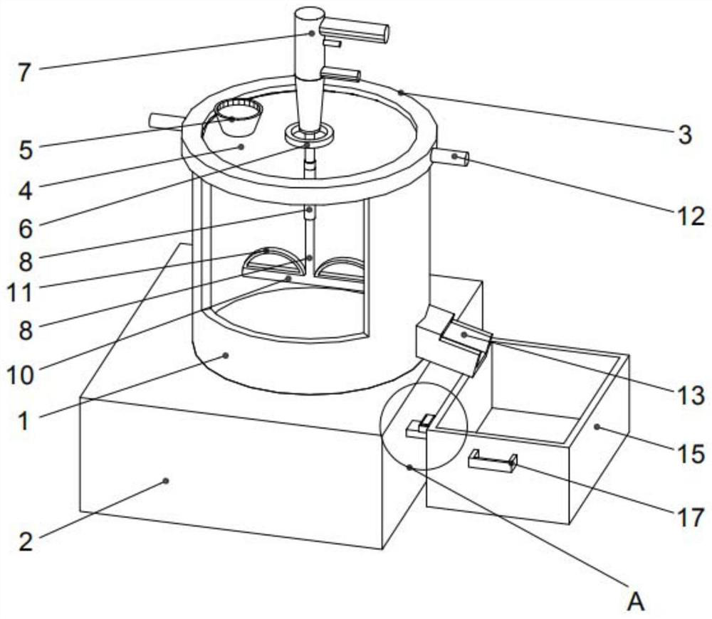
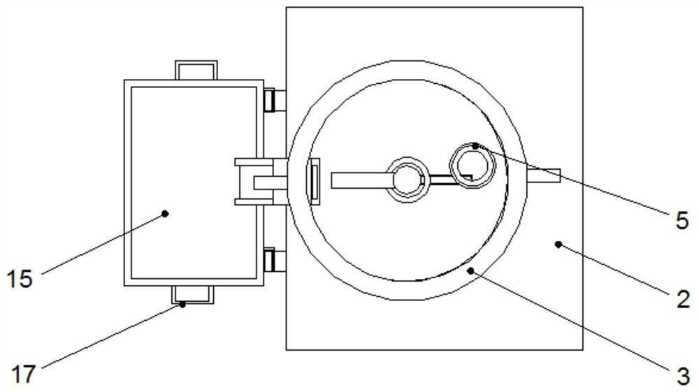
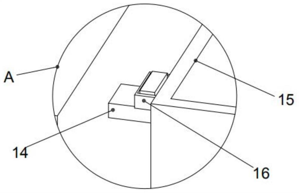
[0021] Example: such as figure 1 , figure 2 and image 3 As shown, a kind of construction putty powder mixing device of the present invention comprises a mixing tank 1 and a base 2, the bottom of the mixing tank 1 is provided with a base 2, the top of the mixing tank 1 is provided with a cover 3, and the cover 3 and the mixing tank 1 are threaded Fixed, the surface of the cover 3 is provided with tempered glass 4, the tempered glass 4 is embedded on the surface of the cover 3, the top of the cover 3 is provided with a feed port 5, the feed port 5 and the cover 3 are fixed by buckles, the tempered glass 4 The middle part is provided with a through hole 6, and the inside of the through hole 6 is provided with an electric drill 7, and the electric drill 7 and the through hole 6 are fixed by interspersing. The rod 9 and the sleeve rod 8 are fixed by threads, and one end of the threaded rod 9 is provided with a cross bar 10, and the cross rod 10 and the threaded rod 9 are fixed ...
PUM
Abstract
The invention discloses a putty powder mixing device for a building. The putty powder mixing device comprises a stirring barrel and a base, the base is arranged at the bottom of the stirring barrel, acover is arranged at the top of the stirring barrel, the cover and the stirring barrel are fixed through threads, tempered glass is arranged on the surface of the cover, the tempered glass is embedded in the surface of the cover, and a feeding port is formed in the top of the cover. The feeding port and the cover are fixed through a buckle, a through hole is formed in the middle of the tempered glass, an electric drill is arranged in the through hole, the electric drill and the through hole are fixed in an inserted mode, a sleeve rod is arranged at the output end of the electric drill, a threaded rod is arranged at one end of the sleeve rod, and the threaded rod and the sleeve rod are fixed through threads. Through the arranged base, space is provided for discharging, convenience is improved, through the arranged electric drill, rotation of the stirring blades is achieved, the working efficiency is improved, through the arranged tempered glass, the real-time monitoring function in thestirring barrel is achieved, safety is improved, through the arranged feeding port, needed materials are put in, and convenience is improved.
Description
technical field [0001] The invention relates to a mixing device, in particular to a mixing device for construction putty powder. Background technique [0002] In interior decoration, it is sometimes necessary to apply putty to the wall. The quality of putty mixing is directly related to the effect of the wall. Therefore, it is necessary to fully mix the putty and glue in the process of mixing putty. [0003] At present, the existing mixing method is to use a stirring rod to stir the putty, but since the stirring rods are all fixed, when the mixing bucket is shallow or deep, it will cause a lot of inconvenience to the operator, such as placing an electric drill close to the inside of the bucket. If it is tight, the putty in the barrel is likely to be thrown on the operator or the electric drill. When the stirring rod is long, it is inconvenient for the operator to hold the electric drill. Therefore we make improvement to this, propose a kind of building putty powder mixing d...
Claims
Application Information
Patent Timeline
Application Date:The date an application was filed.
Publication Date:The date a patent or application was officially published.
First Publication Date:The earliest publication date of a patent with the same application number.
Issue Date:Publication date of the patent grant document.
PCT Entry Date:The Entry date of PCT National Phase.
Estimated Expiry Date:The statutory expiry date of a patent right according to the Patent Law, and it is the longest term of protection that the patent right can achieve without the termination of the patent right due to other reasons(Term extension factor has been taken into account ).
Invalid Date:Actual expiry date is based on effective date or publication date of legal transaction data of invalid patent.