Cleaning machine workpiece transposition device

A technology for cleaning machines and workpieces, which is applied to cleaning methods and utensils, chemical instruments and methods, etc., can solve the problems of low practicability, difficult cleaning, and difficulty in adjusting the installation position of cleaning machines, etc., and achieves the goal of increasing practicability and improving practicability Effect

Inactive Publication Date: 2021-03-12
无锡德工机械制造有限公司
View PDF0 Cites 0 Cited by
  • Summary
  • Abstract
  • Description
  • Claims
  • Application Information

AI Technical Summary

Problems solved by technology

[0004]However, when the above-mentioned technical solutions are actually used, there are still many shortcomings;
[0005] 1. Since the device uses a gantry structure, in actual use, only the workpiece fixed inside can be transposed longitudinally. When cleaning, the cleaning machine can only clean the longitudinal surface of the workpiece. The two sides on both sides of the gantry On the side, it is necessary to manually adjust the position of the cleaning machine or re-fix the workpiece to clean the side. Usually, the cleaning machine is generally installed in a fixed position and difficult to adjust, resulting in difficult cleaning;
[0006] 2. Since the device uses a hydraulic rod and a positioning pin seat to fix the workpiece, in actual use, because the size of the gantry structure is fixed, the positioning pin seat located on the inner side is fixedly connected with the gantry, so it can only hold the workpiece when clamping. For workpieces of the same width, it is necessary to readjust the installation position of the door frame when clamping large workpieces, resulting in the disadvantage of low practicability of the device

Method used


Image

  • Cleaning machine workpiece transposition device
  • Cleaning machine workpiece transposition device
  • Cleaning machine workpiece transposition device

Examples


Embodiment Construction

[0026] The following will clearly and completely describe the technical solutions in the embodiments of the present invention with reference to the accompanying drawings in the embodiments of the present invention. Obviously, the described embodiments are only some, not all, embodiments of the present invention. Based on the embodiments of the present invention, all other embodiments obtained by persons of ordinary skill in the art without making creative efforts belong to the protection scope of the present invention.

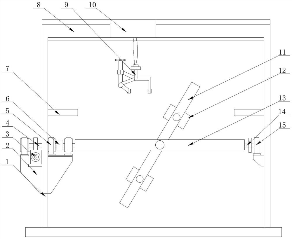
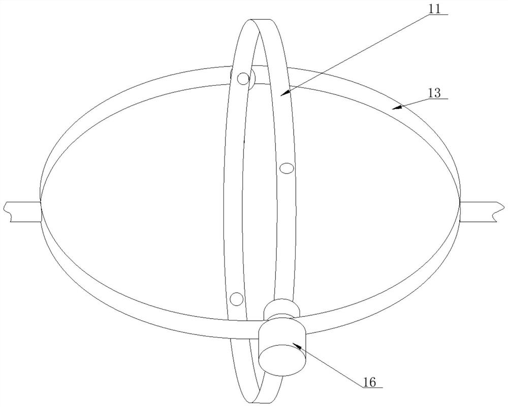
[0027] as attached Figure 1-4 A cleaning machine workpiece indexing device shown includes a gantry 1 composed of two columns, the bottom of the gantry 1 is slidable, the gantry 1, and the left and right columns of the gantry 1 are respectively fixed with brackets 2, The bearing housing 15 and the top of the bracket 2 are fixedly equipped with a hydraulic adjustment mechanism 3 and a rolling bearing housing 5. The center of the bearing housing 15 is sleeved wi...


PUM


Abstract

The invention discloses a cleaning machine workpiece transposition device, and particularly relates to the field of cleaning equipment. The device comprises a portal frame consisting of two upright posts, the bottom end of the portal frame is slidable, the left and right upright posts of the portal frame are provided with a support and a bearing seat respectively, and the top end of the support isprovided with a hydraulic adjusting mechanism and a rolling bearing seat; and the center of the bearing seat is rotationally sleeved with an outer ring, a navigation hanging bracket is installed at the top end of the portal frame, a navigation hanging mechanism is movably installed on the top face of the navigation hanging bracket, and the other end of a gear coupling is fixedly connected with the outer ring and an inner ring through the rolling bearing seat and a connecting shaft. According to the device, a double-ring structure is adopted for clamping a machine part, so that the machine part located in the double-ring structure can perform transverse rotation and longitudinal rotation, all-directional steering of the machine part is achieved, the cleaning machine can clean the machine part in an all-directional mode, the practicability of the device is greatly improved, and the trouble of reinstalling the machine part or carrying out secondary cleaning is saved.

Description

technical field [0001] The invention relates to the technical field of cleaning equipment, and more specifically, the invention is a workpiece indexing device for a cleaning machine. Background technique [0002] At present, in the machinery manufacturing industries such as automobiles, motorcycles, tractors, and internal combustion engines, in order to improve the cleanliness of mechanical parts before installation, some have been cleaned by a through-type cleaning machine. When cleaning the bottom surface of some special workpieces, it is necessary to install a workpiece indexing device in one of the special cleaning rooms of the cleaning machine. In the working room, each shaft section is equipped with a turntable that can hold the workpiece, and the three-cylinder positioning drive mechanism drives the long axis to carry the workpiece to the position. Under normal circumstances, it can achieve the required technical effect, but due to The radius of gyration is large, so...

Claims


Application Information

Patent Timeline
Patent Type & Authority Applications(China)
IPC IPC(8): B08B13/00
CPCB08B13/00
Inventor 杨斌卢永芳
Owner 无锡德工机械制造有限公司
Why Eureka
Try Eureka