
Copper-clad plate surface copper foil forming processing technology

A technology for forming and processing copper clad laminates, applied in metal processing and other directions, can solve the problems of inability to cut copper foil, reduce equipment applicability, and be prone to beveled copper foil, so as to improve flexibility, improve applicability, and improve smoothness. Effect

Inactive Publication Date: 2021-03-12
张小闯
View PDF0 Cites 3 Cited by
  • Summary
  • Abstract
  • Description
  • Claims
  • Application Information

AI Technical Summary

Problems solved by technology

[0005] The invention can solve the problem that the existing equipment cannot level the side wall of the placed copper foil when cutting the copper foil on the surface of the copper clad laminate, and the copper foil is prone to chamfering after cutting, thereby reducing the cost of cutting the copper foil. In addition, the copper foil cannot be driven to rotate, and the copper foil cannot be cut from different angles, thereby reducing the applicability of the equipment. At the same time, it cannot be moved according to the required cutting size of the copper foil, thereby reducing the flexibility of the equipment. , and, when the copper foil is cut, the cutting place cannot be scraped and pressed, and the copper foil is prone to displacement during cutting, thereby reducing the effect of copper foil cutting and reducing the smoothness of the copper foil incision.

Method used


Image

  • Copper-clad plate surface copper foil forming processing technology
  • Copper-clad plate surface copper foil forming processing technology
  • Copper-clad plate surface copper foil forming processing technology

Examples


Embodiment Construction

[0032] The embodiments of the present invention will be described in detail below with reference to the accompanying drawings, but the present invention can be implemented in many different ways defined and covered by the claims.

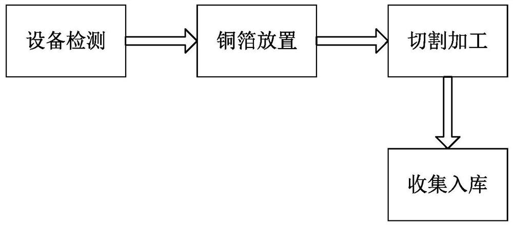
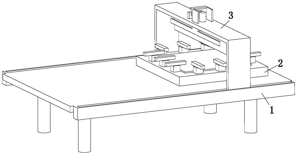
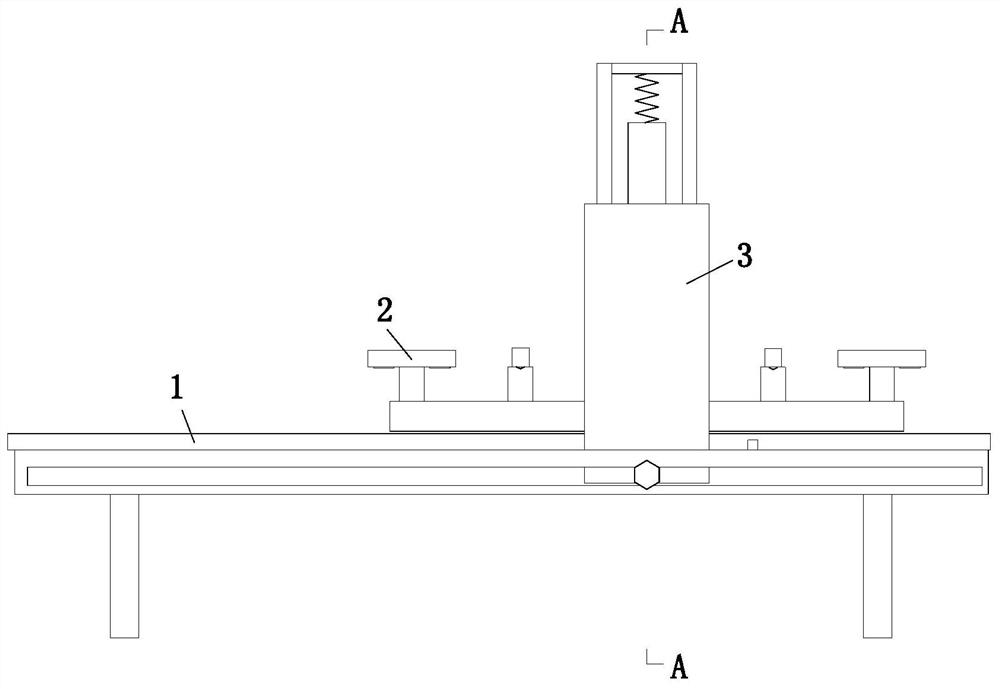
[0033] Such as Figure 1 to Figure 7 As shown, in order to achieve the above object, the present invention adopts the following technical scheme, a copper clad laminate surface copper foil forming process, which uses a copper clad laminate surface copper foil forming processing equipment, the copper clad laminate surface copper foil forming processing equipment includes The support table 1, the receiving device 2 and the cutting device 3, the specific method of cutting the copper foil with the copper foil forming processing equipment on the surface of the copper clad laminate is as follows:

[0034] S1. Equipment inspection: Before the equipment is used, the equipment is routinely inspected manually;

[0035] S2. Copper foil placement: place the mu...


PUM


Abstract

The invention relates to a copper-clad plate surface copper foil forming processing technology. A supporting table, a bearing device and a cutting device are included, the upper end of the supportingtable is connected with the bearing device through a bearing, and the cutting device is arranged above the bearing device. According to the technology, the problems that when existing equipment is used for cutting copper foil on the surface of a copper-clad plate, the side wall of the placed copper foil cannot be leveled, and the copper foil is prone to suffering from beveling after being cut, consequently, the copper foil cutting effect is reduced, the copper foil cannot be driven to rotate, the copper foil cannot be cut from different angles, consequently, equipment adaptability is reduced,meanwhile, the equipment cannot move according to the required cutting size of the copper foil, consequently, the flexibility of the equipment is reduced, the cut position cannot be scraped and pressed during copper foil cutting, the copper foil is prone to displacement during cutting, consequently, the copper foil cutting effect is reduced, and smoothness of the cut opening of the copper foil isreduced can be solved.

Description

technical field [0001] The invention relates to the technical field of production of copper-clad laminates, in particular to a process for forming copper foil on the surface of copper-clad laminates. Background technique [0002] The copper foil on the surface of the copper clad laminate is a negative electrolytic material. It is a thin, continuous metal foil deposited on the base layer of the circuit board. It acts as a conductor of the PCB. It is easily bonded to the insulating layer and accepts printing The protective layer forms a circuit pattern after corrosion. Copper foil has low surface oxygen characteristics and can be attached to various substrates, such as metals, insulating materials, etc., and has a wide temperature range. [0003] At present, the existing equipment usually has the following deficiencies when cutting the copper foil on the surface of the copper clad laminate: 1. The existing equipment cannot level the side wall of the placed copper foil, and the...

Claims


Application Information

Patent Timeline
IPC IPC(8): B26D1/06B26D7/02B26D7/08
CPCB26D1/065B26D7/025B26D7/08
Inventor 张小闯李海波李梦然
Owner 张小闯
Learn More