Automatic laying head and laying method of composite material grid member

A composite material and placement head technology, which is applied in the field of automatic placement head and placement of composite mesh components, can solve problems such as limiting the design space of the grid structure, increasing the volume of the placement head, and clogging of prepregs. To achieve the effect of reducing lateral volume, improving quality and reducing lateral width

Active Publication Date: 2022-07-15
HARBIN INST OF TECH
View PDF0 Cites 0 Cited by
  • Summary
  • Abstract
  • Description
  • Claims
  • Application Information

AI Technical Summary

Problems solved by technology

Common grid member laying heads mostly use rollers for refeeding, and this mechanism is prone to blockage of prepreg in the tow channel during the refeeding process; Chances are that the volume of the placement head becomes larger
When multiple placement heads are used for simultaneous laying, the spacing of the ribs will be limited by the size of the grid placement head structure, which limits the design space of the grid structure
The common grid laying head, the clamping and shearing mechanism needs to use the wire guide groove, which will cause some interference to the prepreg feeding

Method used


Image

  • Automatic laying head and laying method of composite material grid member
  • Automatic laying head and laying method of composite material grid member
  • Automatic laying head and laying method of composite material grid member

Examples


Embodiment Construction

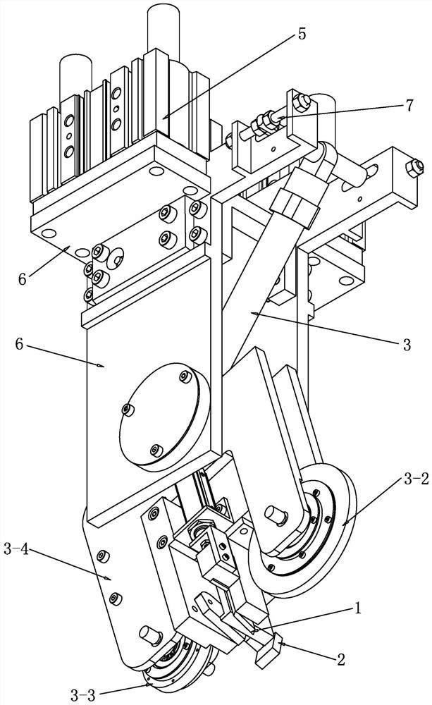
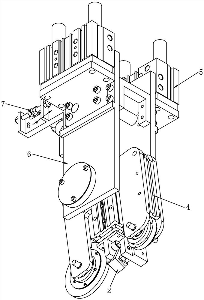
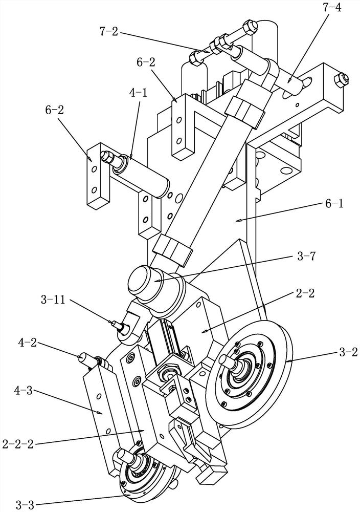
[0024] see Figure 1-Figure 5 As shown, an automatic laying head of a composite grid member in this embodiment includes a shearing mechanism 1, a clamping mechanism 2, a re-feeding mechanism 3 and a tow guide assembly 4; it also includes a pressing cylinder 5, a connection Frame 6 and balance adjustment mechanism 7, the re-feeding mechanism 3 includes a rotating cylinder 3-1, a working pressure roller 3-2, an auxiliary pressure roller 3-3 and a support frame 3-4; the piston rod end of the rotating cylinder 3-1 The part is rotatably connected with the support frame 3-4, the support frame 3-4 is rotatably connected with the connecting frame 6, the connecting frame 6 is connected with the piston rod of the pressing cylinder 5, the cylinder body of the pressing cylinder 5 is connected with the existing equipment, and the working pressure is The roller 3-2 and the auxiliary pressing roller 3-3 are arranged at intervals and can be rotatably arranged on the support frame 3-4, and in ...


PUM


Abstract

An automatic laying head and a laying method for a composite material grid member, comprising a shearing mechanism, a clamping mechanism, a re-feeding mechanism and a tow guide assembly; further comprising a pressing cylinder, a connecting frame and a balance adjusting mechanism, the weight The feeding mechanism includes a rotating cylinder, a working pressure roller, an auxiliary pressure roller and a support frame; the support frame is rotatably connected with the connecting frame, and the working pressure roller and the auxiliary pressure roller are arranged at intervals and can be rotatably arranged on the support frame. The balance adjustment mechanism It is arranged above the re-feeding mechanism, and the balance adjustment mechanism includes an adjustment rod, a connecting rod and a positioning element. On each connecting rod, the position of the adjusting rod is positioned by a positioning element arranged on the connecting rod, and the cylinder body of the rotary cylinder is rotatably arranged on the adjusting rod. The invention ensures that the pressing roller can be perpendicular to the laying plane during laying, the tow is not blocked when re-feeding, and the clamping and shearing mechanism does not occupy the tow channel.

Description

technical field [0001] The invention relates to a composite material laying equipment and a process, in particular to an automatic laying head and a laying method of a composite material grid member. Background technique [0002] Composite mesh members have the characteristics of high specific stiffness, high strength, and anti-vibration, and are widely used in aerospace, vehicles, medicine, and weaponry. Although composite mesh components have better performance than metal materials, they are more difficult and costly to manufacture. At present, the manufacturing technologies of composite mesh components include automatic filament winding, resin molding transfer molding, 3D printing and automatic placement technology. The automatic placement technology has the process characteristics of high efficiency, high quality and low scrap rate, and is especially suitable for the forming of complex grid components. There is still a big gap between the automatic laying equipment of ...

Claims


Application Information

Patent Timeline
Patent Type & Authority Patents(China)
IPC IPC(8): B29C70/38B29L28/00
CPCB29C70/382B29C70/384B29L2028/00
Inventor 韩振宇张佳海孙守政张鹏富宏亚刘禹华
Owner HARBIN INST OF TECH
Why Eureka
Try Eureka