Electronic component mounting method and apparatus

An installation method and a technology for installation devices, which are applied in the direction of assembling printed circuits of electrical components, electrical components, electrical components, etc., can solve the problems of worthless suction nozzle 9 moving vertically and reducing productivity, etc.

Inactive Publication Date: 2003-10-15
PANASONIC CORP
View PDF3 Cites 1 Cited by
  • Summary
  • Abstract
  • Description
  • Claims
  • Application Information

AI Technical Summary

Problems solved by technology

In this case, it is necessary to move up the suction nozzle 9 again after identifying the component, and after completing the installation of the downward movement of the suction nozzle, so there is a problem of vertical movement of the suction nozzle 9 that is worthless, resulting in a decrease in productivity

Method used


Image

  • Electronic component mounting method and apparatus
  • Electronic component mounting method and apparatus
  • Electronic component mounting method and apparatus

Examples


Embodiment Construction

[0063] Before describing the working sequence of the present invention, it is reminded that like parts are indicated by the same reference numerals in all corresponding drawings.

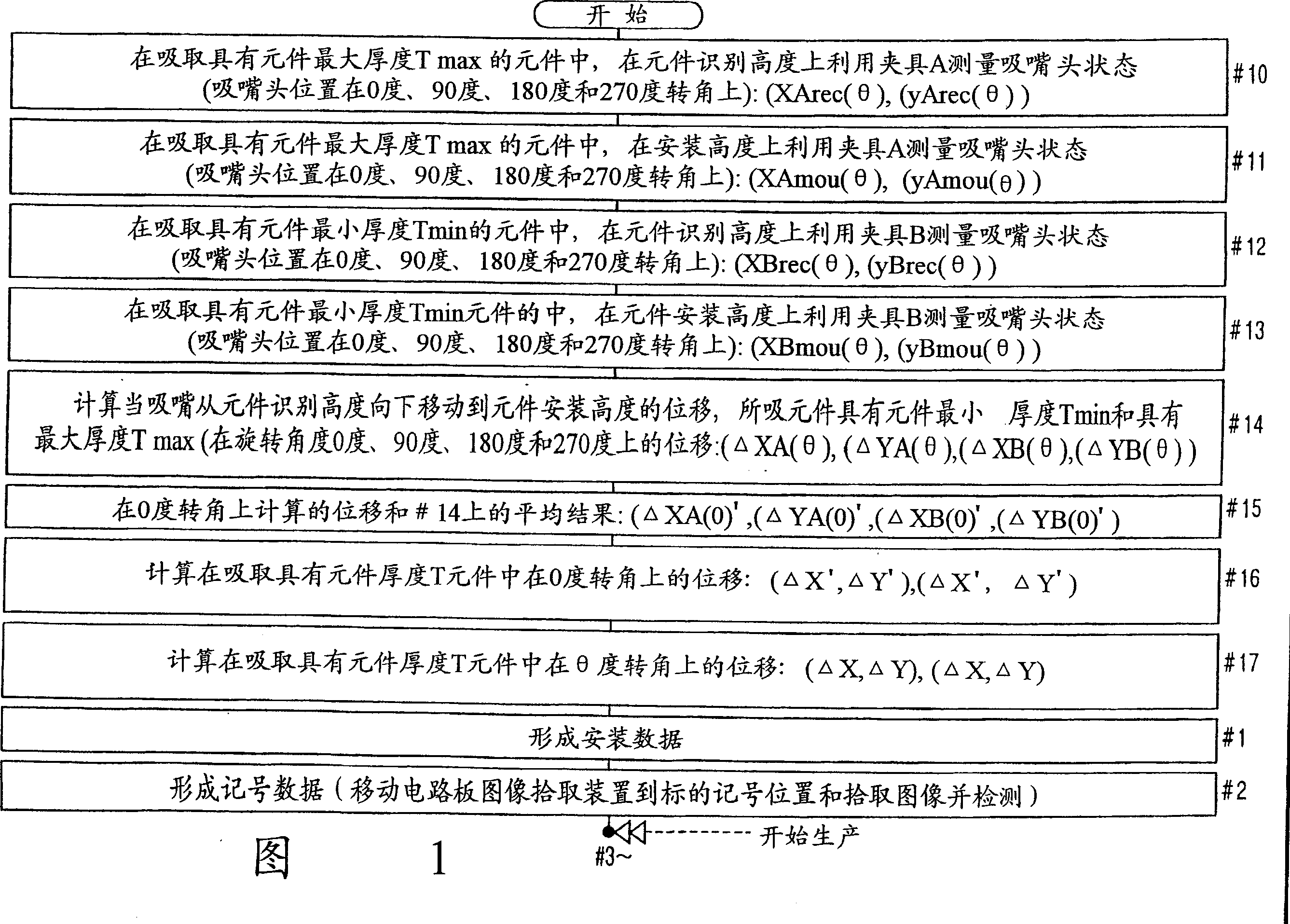
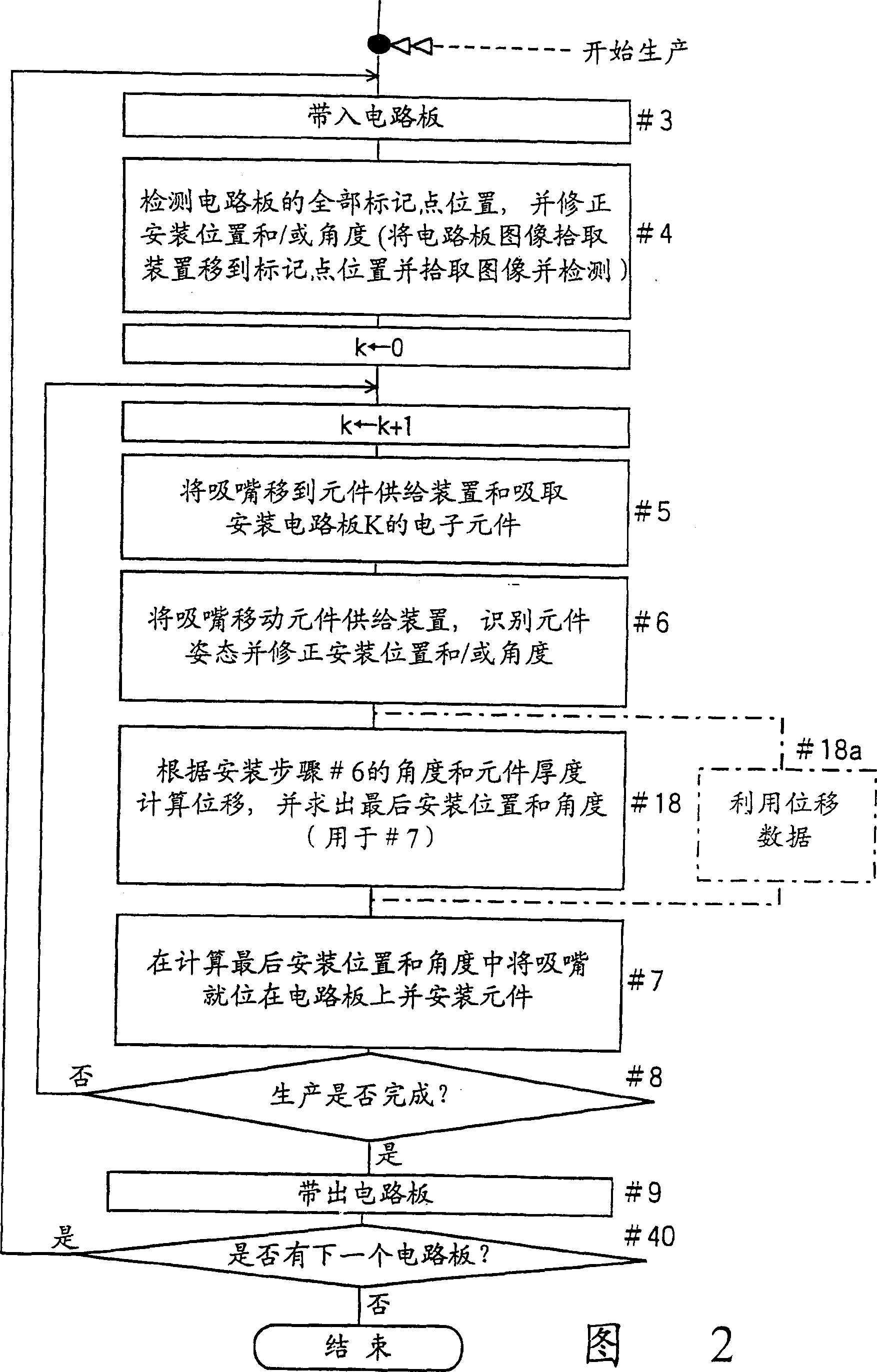
[0064] An electronic component installation method and device according to an embodiment of the present invention will be described below with reference to FIGS. 1 to 6 . Note that all structures of the electronic component mounting device and component mounting head are almost similar to those of the reference Figure 7 and 12 The structure of the prior art is described, so those structural parts that are the same as those of the prior art structure will not be further described.

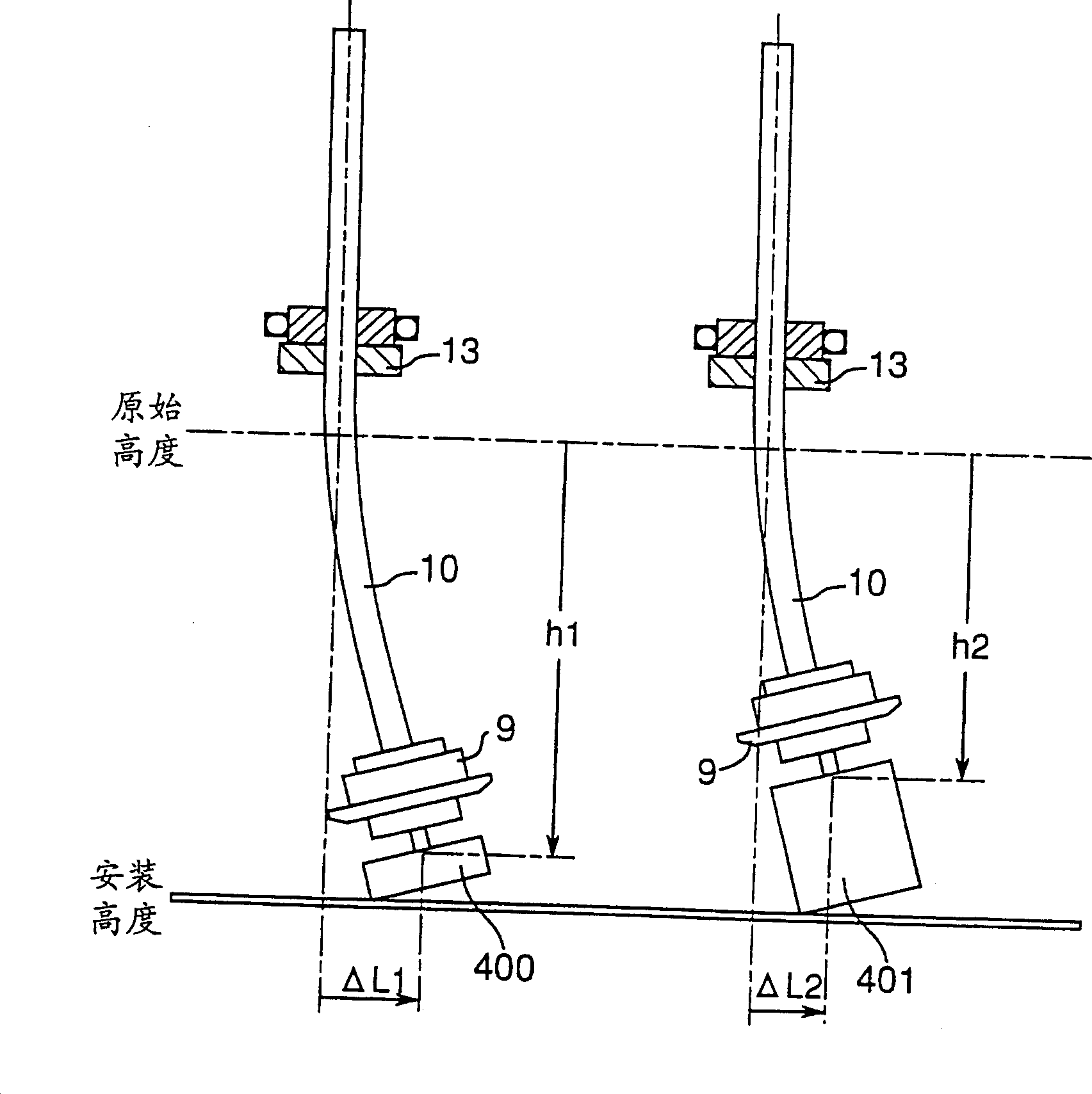
[0065] In this embodiment, as shown in Figure 1, more important than the production of the circuit board is to measure the displacement of the suction nozzle head according to the bending of the axis when the suction nozzle moves vertically and rotationally before production, for example, to obtain the displacement produ...


PUM


Abstract

The behavior of a nozzle tip is measured with a jig when the suction nozzle moves vertically and rotatively before the start of production. The nozzle tip displacement is formulated from the results with a component thickness and a mounting angle used as parameters, and the parameters are corrected according to the component thickness and the final mounting angle of the electronic component to be mounted in the production stage, to finish high class mounting.

Description

technical field [0001] The invention relates to a component mounting method and device for automatically mounting components on a circuit board. Background technique [0002] Figure 7 A structural example of a prior art electronic component mounting apparatus is shown in FIG. 8 , and a flow chart of its operation control program is shown in FIG. 8 . Now compare Figure 7 and 8 illustrate prior art electronic component mounting methods. [0003] Such as Figure 9 As shown, a set of installation patterns 2 (2A, 2B, 2C) and marking points 3 (3A, 3B, 3C) are formed on the circuit board 1, and the required electronic components are installed on the installation pattern 2 to complete the production of the circuit board . In this case, the marking points 3 are used to correct mounting positions that are precisely changed every time according to the shrinkage of the circuit board occurring in the baked circuit board mounting pattern and the state of the circuit board 1 supported...

Claims


Application Information

Patent Timeline
Patent Type & Authority Patents(China)
IPC IPC(8): B23P19/00H05K13/04H05K13/08
CPCH05K13/08H05K13/0413H05K13/0409H05K13/0812Y10T29/4913Y10T29/49131Y10T29/49133Y10T29/53087Y10T29/53091Y10T29/53174Y10T29/53178Y10T29/53183Y10T29/53191
Inventor 味村好裕吉田典晃奥田修
Owner PANASONIC CORP
Why Eureka
Try Eureka