Engine cylinder body lifting, rotating and conveying device

A technology of engine cylinders and conveying devices, which is applied in the direction of hoisting devices, lifting frames, etc., can solve the problems of low work efficiency, backward operation methods, poor safety and reliability, etc., and achieve the effect of simple and reasonable structure and high work efficiency

Pending Publication Date: 2021-03-12
GUANGXI YUCHAI MASCH CO LTD
View PDF0 Cites 1 Cited by
  • Summary
  • Abstract
  • Description
  • Claims
  • Application Information

AI Technical Summary

Problems solved by technology

[0002] During the production and assembly process of the engine, the engine cylinder block components need to be assembled in separate lines. Due to the limitation of the production site space required by the process, there are inevitably height dif

Method used


Image

  • Engine cylinder body lifting, rotating and conveying device
  • Engine cylinder body lifting, rotating and conveying device
  • Engine cylinder body lifting, rotating and conveying device

Examples


Embodiment Construction

[0019] The specific embodiments of the present invention will be described in detail below in conjunction with the accompanying drawings, but it should be understood that the protection scope of the present invention is not limited by the specific embodiments.

[0020] Unless expressly stated otherwise, throughout the specification and claims, the term "comprise" or variations thereof such as "includes" or "includes" and the like will be understood to include the stated elements or constituents, and not Other elements or other components are not excluded.

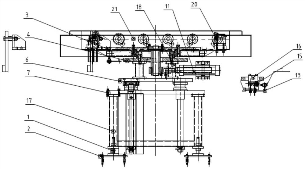
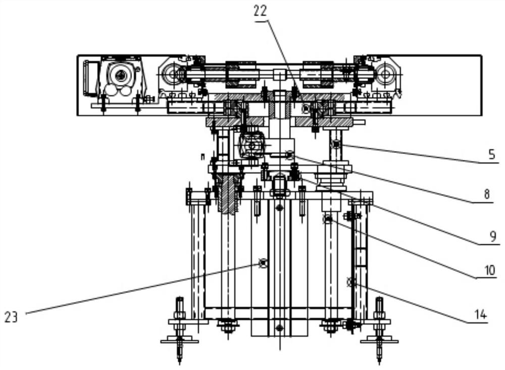
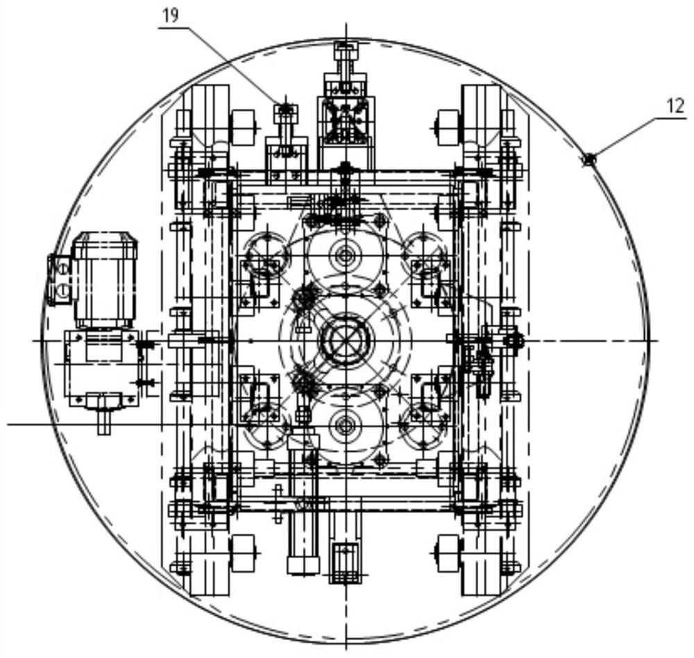
[0021] figure 1 It is a front structural schematic view of an engine cylinder block lifting and turning conveying device according to an embodiment of the present invention. figure 2 It is a schematic side view structure diagram of an engine cylinder block lifting and turning conveying device according to an embodiment of the present invention. image 3 It is a top structural schematic diagram of an engine cylinder block...


PUM


Abstract

The invention discloses an engine cylinder body lifting, rotating and conveying device. The engine cylinder body lifting, rotating and conveying device comprises a support, a plurality of foundation adjusting assemblies, a mounting plate, a plurality of lifting cylinders, a lifting plate, a plurality of supporting legs, a bearing lower mounting plate, a line body mounting base, a line body, a rotating cylinder mounting base, a rotating cylinder connector assembly and a rotating shaft assembly; the foundation adjusting assemblies are fixed below the support, and can adjust the height and the level of the support; the mounting plate is fixed above the support; the multiple lifting cylinders are mounted on the mounting plate, and the front end of a piston rod of each lifting cylinder is connected with a connector; the lifting plate is arranged above the mounting plate, the connectors are fixed to the lifting plate, and the lifting plate ascends and descends through pushing and pulling ofa plurality of guide rod assemblies and the lifting cylinders; and the bearing lower mounting plate is mounted above the supporting legs. Therefore, the engine cylinder body lifting, rotating and conveying device is simple and reasonable in structure, safe, reliable and high in working efficiency.

Description

technical field [0001] The invention relates to the technical field of engine manufacturing, in particular to an engine cylinder block lifting and turning conveying device. Background technique [0002] During the production and assembly process of the engine, the engine cylinder block components need to be assembled in separate lines. Due to the limitation of the production site space required by the process, there are inevitably height differences and flow direction changes between certain processes of the production conveyor line. Through manual hoisting and circulation, the operation method is relatively backward, the work efficiency is low, and the safety and reliability are poor. [0003] The information disclosed in this Background section is only for enhancing the understanding of the general background of the present invention and should not be taken as an acknowledgment or any form of suggestion that the information constitutes the prior art that is already known t...

Claims


Application Information

Patent Timeline
IPC IPC(8): B66F7/16B66F7/28
CPCB66F7/16B66F7/28
Inventor 卢福才梁杰朱明贤陈邦永钟林
Owner GUANGXI YUCHAI MASCH CO LTD
Why Eureka
Try Eureka