
Sludge drying structure

A sludge drying and drying technology, applied in the direction of dehydration/drying/concentrated sludge treatment, etc., can solve the problems of poor drying effect and low waste heat utilization rate, achieve a reasonable and simple structure arrangement, and reduce vortex generation , the effect of uniform gas distribution

Pending Publication Date: 2021-03-12
浙江远能环保设备有限公司
View PDF0 Cites 0 Cited by
  • Summary
  • Abstract
  • Description
  • Claims
  • Application Information

AI Technical Summary

Problems solved by technology

[0003] In view of this, the present invention aims to propose a sludge drying structure to solve the problems of low waste heat utilization rate and poor drying effect in the low-temperature sludge drying process

Method used


Image

  • Sludge drying structure
  • Sludge drying structure
  • Sludge drying structure

Examples


Embodiment Construction

[0049] It should be noted that, in the case of no conflict, the embodiments of the present invention and the features in the embodiments can be combined with each other.

[0050]In describing the present invention, it should be understood that the terms "center", "longitudinal", "transverse", "upper", "lower", "front", "rear", "left", "right", The orientations or positional relationships indicated by "vertical", "horizontal", "top", "bottom", "inner", "outer", etc. are based on the orientation or positional relationships shown in the drawings, and are only for the convenience of describing the present invention Creation and simplification of description, rather than indicating or implying that the device or element referred to must have a specific orientation, be constructed and operate in a specific orientation, and therefore should not be construed as limiting the invention. In addition, the terms "first", "second", etc. are used for descriptive purposes only, and should not...


PUM


Abstract

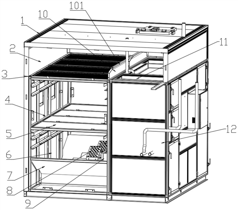
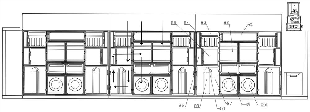
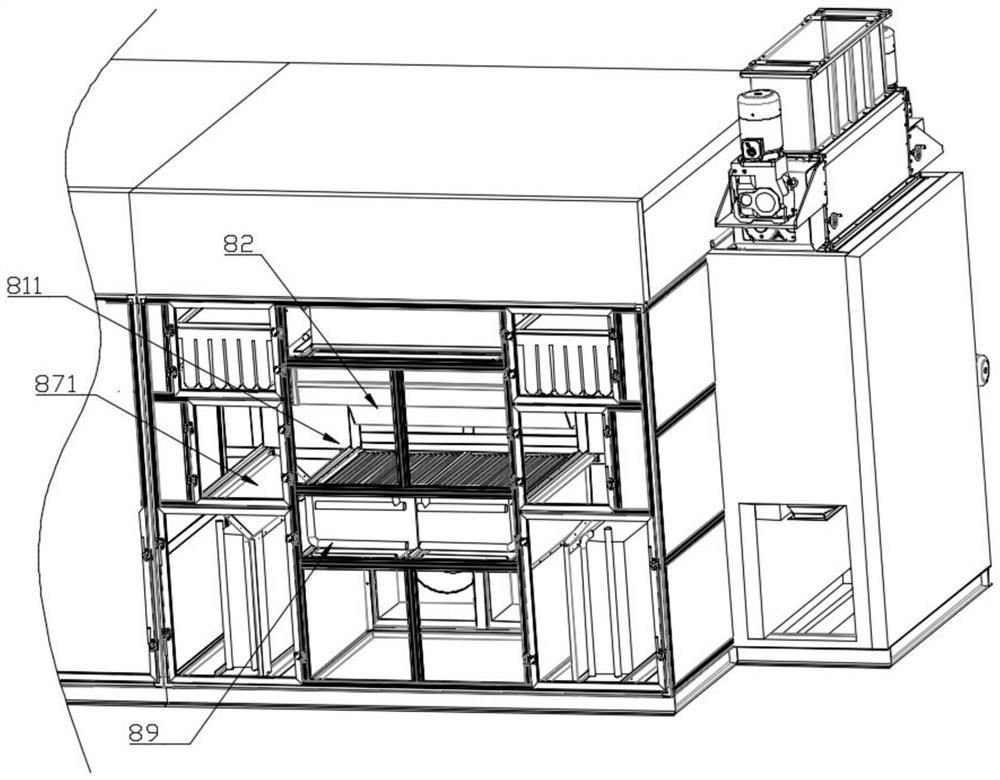
The invention provides a sludge drying structure which comprises a drying area and a heating area, hot air output by the heating area enters the drying area, and air in the drying area flows into theheating area through an air passing plate; and an included angle is formed between the gas outflow direction of the drying area and an air passing bent part of the air passing plate. According to thedesign position and the design angle of the air passing plate, the problem that circulating gas generates vortexes is fully considered, and vortexes generated in the gas circulation process are reduced to the maximum extent.

Description

technical field [0001] The invention belongs to the field of sludge drying, and in particular relates to a sludge drying structure. Background technique [0002] The necessary process in sewage treatment is sludge drying and dehydration, and the most environmentally friendly technology among the common sludge drying and dehydration methods is low-temperature sludge drying technology, which uses electric energy to directly heat gas to dry sludge , but the biggest problem in this technology is that there is a lot of waste heat and the recycling rate is relatively low. Moreover, in the improved two-stage drying structure technology on the market, using waste heat technology to carry out circulation drying will inevitably generate vortices during gas circulation, causing problems in gas circulation efficiency, and at the same time, the limitations of internal structure design cause uneven gas circulation , poor degree of drying and so on. Contents of the invention [0003] I...

Claims


Application Information

Patent Timeline
Patent Type & Authority Applications(China)
IPC IPC(8): C02F11/13
CPCC02F11/13
Inventor 陈少军
Owner 浙江远能环保设备有限公司
Learn More