
Charging device

A technology for supercharging devices, compressors, applied in the components of pumping devices for elastic fluids, non-variable displacement pumps, machines/engines, etc. Circumferential velocity and mass flow, etc., to achieve the effect of improved efficiency and great flexibility

Inactive Publication Date: 2018-03-20
BOSCH MAHLE TURBO SYST GMBH & CO KG
View PDF7 Cites 0 Cited by
  • Summary
  • Abstract
  • Description
  • Claims
  • Application Information

AI Technical Summary

Problems solved by technology

[0003] A disadvantage of the booster devices known in the prior art however is the low peripheral speed and mass flow, i.e. near the surge limit, increased fluid separation and backflow in the diffuser near the bearing housing wall danger
Especially at low peripheral speeds and mass flows, which leads to reduced efficiency

Method used


Image

  • Charging device

Examples


Embodiment Construction

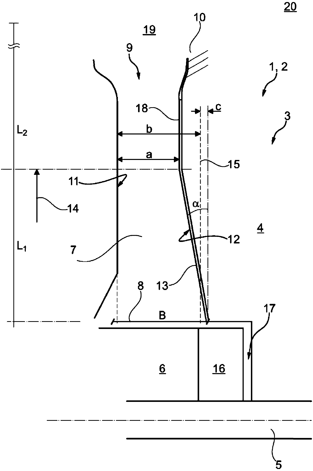
[0015] according to figure 1 , in particular a charging device 1 according to the invention which can be designed as an exhaust-gas turbocharger 2 in a motor vehicle, comprises a compressor 3 and is rotatably mounted on a bearing housing 4 via a compressor wheel 6 arranged thereon. in axis 5. Likewise, the charging device 1 according to the invention comprises a diffuser 7 extending radially from a diffuser inlet 8 on the compressor wheel 6 towards a diffuser outlet 9 on the helical compressor casing 10 . According to the invention, the diffuser 7 is now delimited on the one hand by the diffuser wall 11 and on the other hand by the bearing housing wall 12 . According to the invention, the bearing housing wall 12 is oriented obliquely towards the radial direction 14 at an angle α between 2 and 30° on the first portion arising from the diffuser inlet 8 and brings about a radial direction of the diffuser section 14 Tapering towards the outside. A compressor known from the prio...


PUM


Abstract

A charging device may include a compressor, a bearing housing, a shaft that is rotatably mounted in the bearing housing, a compressor wheel arranged on the shaft, and a diffuser, which may radially extend from a diffuser inlet on the compressor wheel towards a diffuser outlet on a spiral-shaped compressor housing. The diffuser may be delimited by a diffuser wall and a bearing housing wall. A firstsection of the bearing housing wall may be oriented originating from the diffuser inlet by an angle ranging from 2 to 30 degrees obliquely to a radial direction, and may bring about a tapering of thediffuser cross section in the radial direction away from the shaft.

Description

technical field [0001] According to the preamble of claim 1 , the invention relates to a charging device having a compressor and a shaft mounted rotatably in a bearing housing via a compressor wheel arranged thereon. Furthermore, the invention relates to an internal combustion engine with such a charging device. Background technique [0002] From EP0386743A2 is known a general charging device having a compressor and a shaft mounted rotatably in a bearing housing via a compressor wheel arranged thereon. Known supercharging devices additionally have a diffuser which extends radially from a diffuser inlet on the compressor wheel to a diffuser outlet on the helical compressor casing. Here, the diffuser itself tapers relative to its radial length, thereby increasing the pressure and thus achieving an increased efficiency. [0003] A disadvantage of the booster devices known in the prior art however is the low peripheral speed and mass flow, i.e. near the surge limit, increased ...

Claims


Application Information

Patent Timeline
IPC IPC(8): F04D29/44F04D29/66
CPCF04D29/441F04D29/667F05D2220/40F04D17/10F04D29/053F04D29/056
Inventor 谢诺尔·瑟于特鲁迪格·施韦格尔菲利浦·梅茨勒尼古莱·施纳贝尔
Owner BOSCH MAHLE TURBO SYST GMBH & CO KG
Learn More