A kind of electroplating device for faucet manufacturing

A technology for electroplating devices and faucets, which is applied in the direction of electrolytic components, electrolytic processes, cells, etc., can solve problems such as uneven electroplating and faucet movement, and achieve the effects of speeding up water flow, saving time, and speeding up the electroplating process

Active Publication Date: 2021-10-22
FUZHOU YINSHENGWANG SANITARY WARE
View PDF3 Cites 0 Cited by
  • Summary
  • Abstract
  • Description
  • Claims
  • Application Information

AI Technical Summary

Problems solved by technology

[0005] In order to overcome the disadvantage that the current device cannot move the faucet, which may lead to uneven electroplating, the purpose of the present invention is to provide an electroplating device for faucet production that can uniformly and quickly electroplate the faucet

Method used


Image

  • A kind of electroplating device for faucet manufacturing
  • A kind of electroplating device for faucet manufacturing
  • A kind of electroplating device for faucet manufacturing

Examples


Embodiment 1

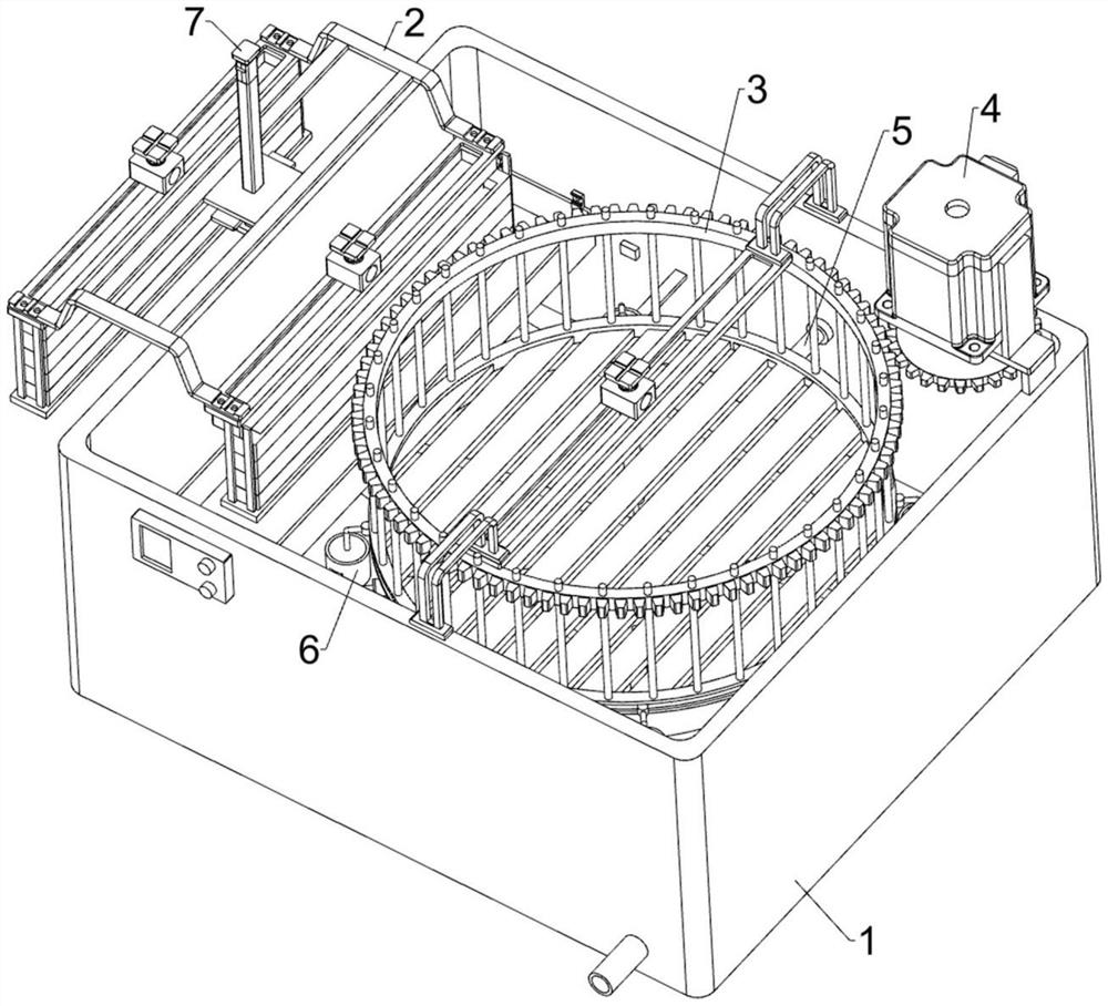
[0030] An electroplating device for faucet manufacturing, such as Figure 1-4 As shown, it includes an electroplating container 1 , an electroplating material supply component 2 and a placement component 3 , the electroplating material supply component 2 is arranged on the left side of the electroplating container 1 , and the placement component 3 is arranged inside the electroplating container 1 .

[0031] When the faucet needs to be electroplated, put the faucet into the placement component 3, then fill the electroplating container 1 with water, and then the electroplating material supply component 2 will cooperate with the placement component 3, so that the electroplating material supply component 2 is part The parts are dissolved, and then the faucet is electroplated. When the electroplating of the faucet is completed, the electroplating container 1 is controlled to discharge the water, thereby stopping the operation of the device.

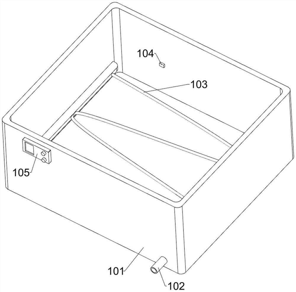
[0032] Electroplating container 1 compr...

Embodiment 2

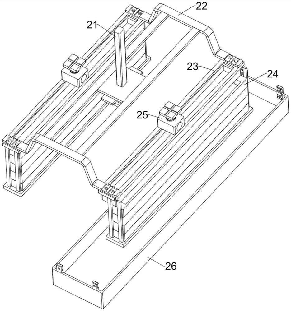
[0039]On the basis of Example 1, such as figure 1 , Figure 5 , Image 6 , Figure 7 and Figure 8 As shown, a rotating assembly 4 is also included. The rotating assembly 4 includes a reduction motor 41, a gear 42 and a ring gear 43. A reduction motor 41 is installed on the upper right side of the electroplating tank 101, and a gear is arranged on the output shaft of the reduction motor 41. 42 , the outer side of the first ring 32 is provided with a ring gear 43 , and the ring gear 43 meshes with the gear 42 .

[0040] When the electroplating work starts, start the deceleration motor 41, the deceleration motor 41 will drive the gear 42 to rotate, and then drive the ring gear 43 to rotate, and then drive the first ring 32 to rotate, thereby driving the faucet to rotate, and then the faucet is electroplated. more evenly.

[0041] Also includes a lifting assembly 5, the lifting assembly 5 includes a support rod 51 and an arc-shaped sloping plate 52, the electroplating pool 1...


PUM


Abstract

The invention relates to an electroplating device, in particular to an electroplating device for faucets. The object of the present invention is to provide an electroplating device for faucet manufacturing which can uniformly and quickly electroplate the faucet. An electroplating device for faucet production and manufacturing includes: an electroplating container; an electroplating material providing component installed on the electroplating container; and a placement component installed on the electroplating container. The invention has an acceleration component, which can speed up the flow of water, thereby further speeding up the electroplating process, saving time and improving production efficiency; the invention has a heater, which can heat the water, thereby accelerating the electrolysis of the chromium plate, and further making the electroplating The effect is better, and it also has a temperature sensor and a temperature controller, which can prevent the temperature from being too high and affect the plating effect.

Description

technical field [0001] The invention relates to an electroplating device, in particular to an electroplating device for faucets. Background technique [0002] The faucet is a common prop used to control the size of the water flow. The faucet is generally made of steel, so the faucet needs to be electroplated to prevent the faucet from rusting. [0003] The patent authorization announcement number is CN207391592U, which discloses an electroplating device for faucet production and manufacturing, including an electroplating pool, a chrome plate and a plating rack. A heater is arranged inside the lower side of the electroplating pool, and the upper middle of the heater is There is a drain outlet near the inner surface of the electroplating pool, and a temperature sensor is installed on the left side of the drain outlet. Although this device increases the effect of electroplating and saves electroplating time, it cannot move the faucet, which may cause Uneven plating. [0004] ...

Claims


Application Information

Patent Timeline
Patent Type & Authority Patents(China)
IPC IPC(8): C25D17/00C25D7/04C25D21/02C25D17/06C25D21/12C25D5/08
CPCC25D5/08C25D7/04C25D17/00C25D17/06C25D21/02C25D21/12
Inventor 齐维金程银华
Owner FUZHOU YINSHENGWANG SANITARY WARE
Why Eureka
Try Eureka