
Electroplating clamp and chuck for printed circuit board

A technology for printed circuit boards and electroplating fixtures, applied in the directions of printed circuits, printed circuit manufacturing, electrical components, etc., can solve the problems of potion polluting the environment, quality problems, waste of production capacity, etc., and achieve the effect of saving costs

Inactive Publication Date: 2021-03-12
SUZHOU LANGCHAO INTELLIGENT TECH CO LTD
View PDF8 Cites 0 Cited by
  • Summary
  • Abstract
  • Description
  • Claims
  • Application Information

AI Technical Summary

Problems solved by technology

[0002] The PCB (printed circuit board, printed circuit board) boards used in the electronics industry need to be electroplated. Electroplating metallizes the holes in the board to achieve the purpose of conduction. During the electroplating process, the board needs to be fixed on the electroplating fixture. The electroplating fixture conducts electricity, and the part of the electroplating fixture clamping the board will be immersed in the electroplating solution, so that the electroplating fixture is also electroplated with copper. If the copper on the electroplating fixture is not removed, it will cause quality problems in the subsequent electroplating PCB. The existing electroplating Fixtures must be deplated. Generally, nitric acid or sulfuric acid / hydrogen peroxide is used to bite off the copper on the fixture. Add 4-5 sets of plating tanks to the plating line to remove the copper on the plating clips. The waste of production capacity and the potion of deplating will cause polluted environment

Method used


Image

  • Electroplating clamp and chuck for printed circuit board

Examples


Embodiment Construction

[0022] The present invention will be described in further detail below in conjunction with the accompanying drawings and embodiments, so that those skilled in the art can implement it with reference to the description.

[0023] It should be understood that terms such as "having", "comprising" and "including" used herein do not exclude the presence or addition of one or more other elements or combinations thereof.

[0024] In addition, it should be noted that, unless otherwise specified and limited, the terms "setting" and "connection" should be understood in a broad sense. For example, it may be a fixed connection or a detachable connection; it may be a direct connection or an indirect connection through an intermediary; it may be an integral connection or an internal communication between two components. Signal transmission and data communication can also be performed between two components. Those of ordinary skill in the art can understand the specific meanings of the above...


PUM


Abstract

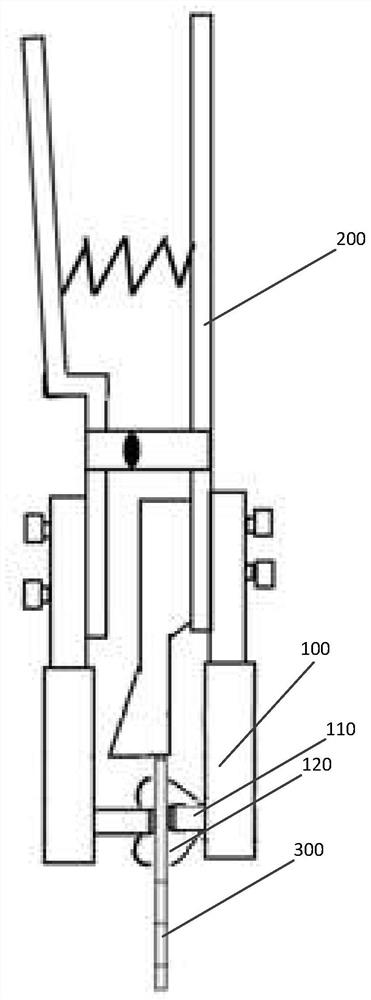
The embodiment of the invention relates to the technical field of integrated circuits, in particular to an electroplating clamp and a chuck for a printed circuit board. The chuck of the electroplatingclamp for the printed circuit board comprises electroplating clamping points and suckers, the suckers are arranged at two ends of the chuck, and the electroplating clamping points are arranged in thesuckers. The suckers are arranged at the clamping points positions, the electroplating clamp clamps a PCB, before the electroplating clamp enters electroplating liquid, the suckers are adsorbed to the surface of the PCB, so that the clamping points positions form vacuum, the clamping points cannot make contact with the electroplating liquid after the electroplating clamp enters a bath solution, all conductive parts on the clamp cannot make direct contact with the electroplating liquid and do not make contact with the electroplating liquid in the electroplating process, and electroplating is completed, therefore, no copper exists on the clamp, deplating is not needed, the cost is saved, and the clamp is relatively environment-friendly.

Description

technical field [0001] Embodiments of the present invention relate to the technical field of integrated circuits, and in particular, relate to an electroplating jig and chuck for printed circuit boards. Background technique [0002] The PCB (printed circuit board, printed circuit board) boards used in the electronics industry need to be electroplated. Electroplating metallizes the holes in the board to achieve the purpose of conduction. During the electroplating process, the board needs to be fixed on the electroplating fixture. The electroplating fixture conducts electricity, and the part of the electroplating fixture clamping the board will be immersed in the electroplating solution, so that the electroplating fixture is also electroplated with copper. If the copper on the electroplating fixture is not removed, it will cause quality problems in the subsequent electroplating PCB. The existing electroplating Fixtures must be deplated. Generally, nitric acid or sulfuric acid / ...

Claims


Application Information

Patent Timeline
IPC IPC(8): C25D17/08C25D7/00H05K3/18
CPCC25D7/00C25D17/08H05K3/188
Inventor 杨琼
Owner SUZHOU LANGCHAO INTELLIGENT TECH CO LTD
Features
  • Generate Ideas
  • Intellectual Property
  • Life Sciences
  • Materials
  • Tech Scout
  • Unparalleled Data Quality
  • Higher Quality Content
  • 60% Fewer Hallucinations
Learn More