Cotton breakage preventing and impurity removing device

An anti-break, cotton technology, used in textiles and papermaking, fiber processing, fiber cleaning machines, etc., can solve the problems of cotton filament tearing, short cotton filament, and reducing cotton processing quality.

Inactive Publication Date: 2021-03-12
刘云翔
View PDF0 Cites 3 Cited by
  • Summary
  • Abstract
  • Description
  • Claims
  • Application Information

AI Technical Summary

Problems solved by technology

[0002] Cotton cleaning is to grab the raw materials from the cotton bale according to the selected ratio, mix them evenly, open them into small cotton blocks or small cotton bundles, remove some impurities and defects, and then integrate a cotton layer with a certain width, thickness or weight. Winding into a cotton roll

Method used


Image

  • Cotton breakage preventing and impurity removing device
  • Cotton breakage preventing and impurity removing device
  • Cotton breakage preventing and impurity removing device

Examples


specific Embodiment approach 1

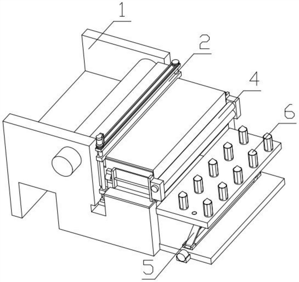
[0040] Combine below Figure 1-17 Description of this embodiment, a cotton anti-breakage and impurity removal device, including a primary conveying mechanism 1, a thickness adaptation mechanism 2, a cotton mass flattening mechanism 3, an elongated output mechanism 4, a lifting mechanism 5, and an impurity removal mechanism 6. The thickness adaptation mechanism 2 is fixedly installed on the primary conveying mechanism 1, the cotton ball flattening mechanism 3 is fixedly installed on the thickness adaptation mechanism 2, the elongation output mechanism 4 is fixedly installed on the thickness adaptation mechanism 2, and the elongation output mechanism 4 is fixedly installed on the On the primary conveying mechanism 1 , the lifting mechanism 5 is fixedly installed on the primary conveying mechanism 1 , and the impurity removal mechanism 6 is fixedly installed on the lifting mechanism 5 .

specific Embodiment approach 2

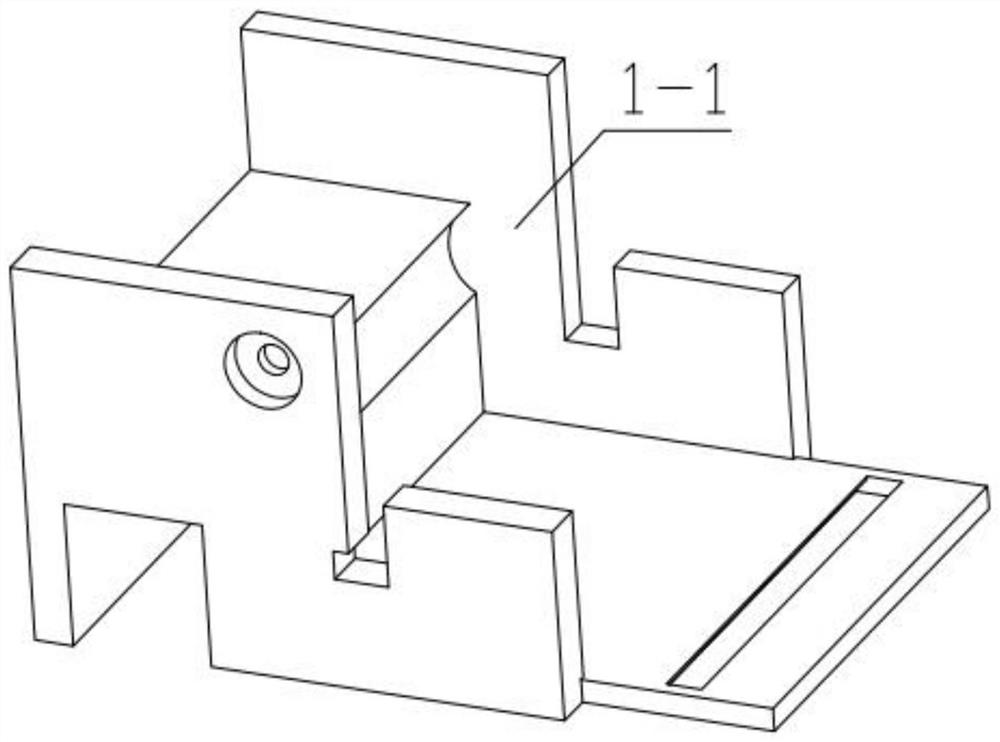
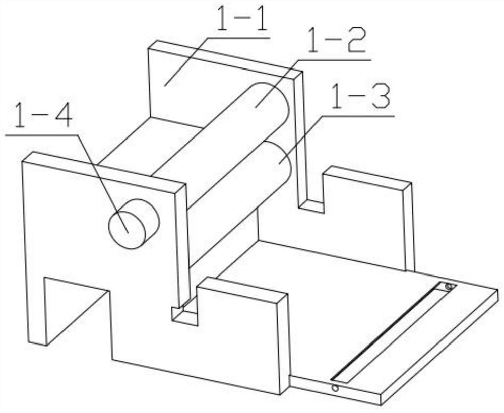
[0042] Combine below Figure 1-17 Describe this embodiment, this embodiment will further explain the first embodiment, the primary conveying mechanism 1 includes a collective mounting frame 1-1, an upper transmission shaft 1-2, a lower transmission shaft 1-3, a motor one 1-4, Upper gear 1-5, lower gear 1-6, motor one 1-4 are fixedly installed on the through hole that is provided with on the collective mounting bracket 1-1, the output end of motor one 1-4 is fixedly installed with upper gear 1-5, The other side of upper gear 1-5 is fixedly installed with upper transmission shaft 1-2, and the other end of upper transmission shaft 1-2 is rotatably installed in the groove that is provided with on collective installation frame 1-1, and upper gear 1-5 and The lower gears 1-6 are meshed, one side of the lower gears 1-6 is rotatably installed in the groove provided on the collective mounting frame 1-1, and the other side of the lower gears 1-6 is fixedly installed with the lower trans...

specific Embodiment approach 3

[0044] Combine below Figure 1-17 Describe this embodiment, this embodiment will further explain the second embodiment, the thickness adaptation mechanism 2 includes an upper mounting plate 2-1, a lower mounting plate 2-2, an upper fixing plate 2-3, a lower fixing plate 2- 4. Motor two 2-5, chain one 2-6, sprocket one 2-7, two-way threaded rod one 2-8, sprocket two 2-9, two-way threaded rod two 2-10, upper mounting plate 2-1 Slidingly installed in the groove provided on the upper fixed plate 2-3, the lower installed plate 2-2 is slidably installed in the groove provided on the lower fixed plate 2-4, the upper fixed plate 2-3 and the lower fixed plate 2-4 All are fixedly installed on the collective mounting frame 1-1, and one end of two-way threaded rod one 2-8 is rotatably installed in the groove provided on the lower fixed plate 2-4, and two-way threaded rod one 2-8 is connected with the lower mounting plate 2-2 Threaded connection, two-way threaded rod one 2-8 is threadedly...


PUM


Abstract

The invention relates to a cotton cleaning device, in particular to a cotton breakage preventing and impurity removing device. The cotton breakage preventing and impurity removing device comprises a primary conveying mechanism, a thickness adapting mechanism, a cotton ball flat spreading mechanism, a lengthening output mechanism, a lifting mechanism and an impurity removing mechanism, wherein thethickness adapting mechanism is fixedly installed on the primary conveying mechanism; the cotton ball flat spreading mechanism is fixedly installed on the thickness adapting mechanism; the lengtheningoutput mechanism is fixedly installed on the thickness adapting mechanism; the lengthening output mechanism is fixedly installed on the primary conveying mechanism; the lifting mechanism is fixedly installed on the primary conveying mechanism; and the impurity removing mechanism is fixedly installed on the lifting mechanism. According to the device, gathered cotton can be flatly spread and then impurities mixed in the cotton are gradually removed, so that the damage to cotton silk can be reduced in the impurity removing process, and the processing quality of the cotton is guaranteed.

Description

technical field [0001] The invention relates to a cotton cleaning device, in particular to a cotton breaking prevention and impurity removal device. Background technique [0002] Cotton cleaning is to grab the raw materials from the cotton bale according to the selected ratio, mix them evenly, open them into small cotton blocks or small cotton bundles, remove some impurities and defects, and then integrate a cotton layer with a certain width, thickness or weight. Winding into a cotton roll. In the prior art, the impurities in the cotton are removed, and multiple sets of roller shafts are used to pull them to remove impurities. However, during the pulling process, the cotton threads are easily torn off, resulting in a large number of short cotton threads, which reduces the cotton quality. processing quality. Contents of the invention [0003] The technical problem mainly solved by the present invention is to provide a cotton anti-breakage and impurity removal device. This ...

Claims


Application Information

Patent Timeline
IPC IPC(8): D01G9/00D01G9/14D01G9/16D01G9/18D01G9/22
CPCD01G9/00D01G9/14D01G9/16D01G9/18D01G9/22
Inventor 刘云翔
Owner 刘云翔
Why Eureka
Try Eureka