Swing type blow-drying device for clothing wrinkles for clothing production
What is AI technical title?
AI technical title is built by Patsnap AI team. It summarizes the technical point description of the patent document.
A swinging, clothing technology, applied in washing devices, household dryers, applications, etc., can solve the problems of inconvenient movement and inability to dry clothes.
Active Publication Date: 2021-03-12
江西美硕实业有限公司
View PDF11 Cites 2 Cited by
Summary
Abstract
Description
Claims
Application Information
AI Technical Summary
This helps you quickly interpret patents by identifying the three key elements:
Problems solved by technology
Method used
Benefits of technology
Problems solved by technology
[0004] In order to overcome the disadvantage that the existing drying device is not easy to move, the blown air will only be in one place of the clothes, and the clothes cannot be dried well, the technical problem is: to provide a device that can automatically clamp and loosen the clothes. Swing drying device for garment production that opens and allows all parts of the garment to be blown by the wind
Method used
Image
Click on the blue label to locate the original text in one second.
Reading with bidirectional positioning of images and text.
Examples
Embodiment 1
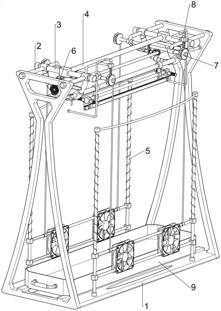
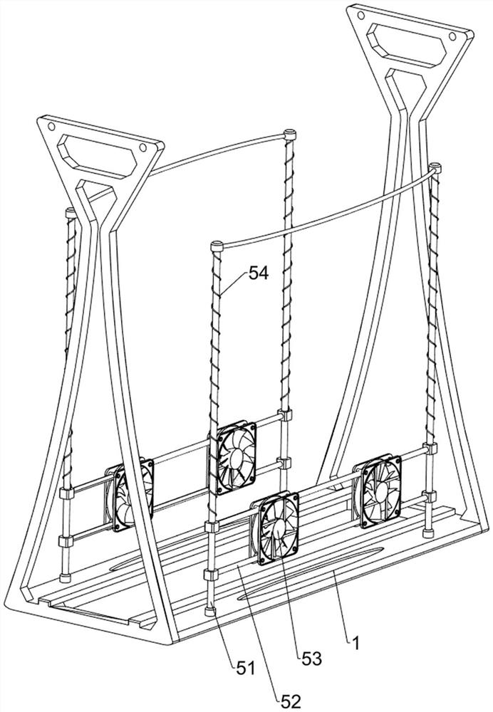
[0028] A swing drying device for garment production, such as figure 1 , figure 2 and image 3 As shown, it includes a base 1, a first bracket 2, a pillar 3, a swing mechanism 4 and a drying mechanism 5. The left and right sides of the base 1 are symmetrically provided with the first bracket 2, and the two adjacent first brackets 2 are evenly spaced. There are pillars 3, a swing mechanism 4 is arranged between the pillars 3, and a drying mechanism 5 is arranged on the base 1.
[0029] When people need to use this device, first people open the swing mechanism 4, then move the clothes between the swing mechanisms 4, then loosen the swing mechanism 4, so that the swing mechanism 4 clamps the clothes, and then people move the swing mechanism 4, The clothes are shaken to shake off the folds, then the drying mechanism 5 can be started, and the drying mechanism 5 can be moved to dry the clothes. After the clothes are dried, people can close the drying mechanism 5 and take off the c...
Embodiment 2
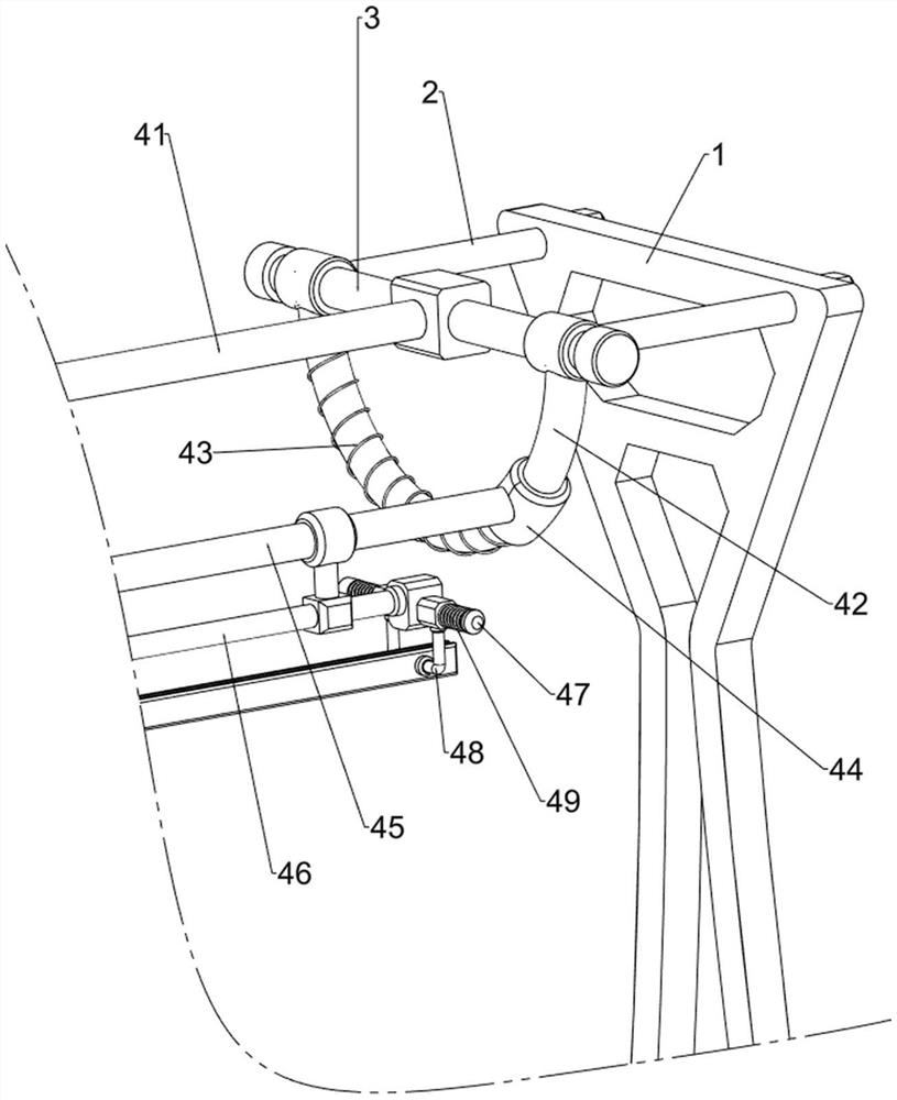
[0034] On the basis of Example 1, such as figure 1 , Figure 4 , Figure 5 , Figure 6 and Figure 7 Shown, also comprise beating mechanism 6, beating mechanism 6 comprises mounting plate 61, motor 62, first rotating shaft 63, beating block 64 and the 3rd support 65, base 1 left side upper part is provided with mounting plate 61, on mounting plate 61 A motor 62 is provided, a first rotating shaft 63 is arranged on the output shaft of the motor 62, and a beating block 64 is arranged symmetrically on the first rotating shaft 63, and the beating block 64 cooperates with the first sliding sleeve 44. Three brackets 65 , the third bracket 65 is connected to the base 1 .
[0035]After people clamp clothes, then just can start motor 62, motor 62 output shafts drive first rotating shaft 63 and beating piece 64 to rotate, when beating piece 64 rotates to contact with first sliding sleeve 44, beating piece 64 passes through the first A sliding sleeve 44 drives the first connecting r...
PUM
Abstract
The invention relates to a blow-drying device, in particular to a swing type blow-drying device for clothing wrinkles for clothing production. The swing type blow-drying device for the clothing wrinkles for clothing production can automatically clamp and loosen clothing and enable all positions of the clothing to be blown by wind. The swing type blow-drying device for the clothing wrinkles for clothing production comprises a base, supporting columns, a swinging mechanism and a drying mechanism, wherein first supports are symmetrically arranged on the two sides of the base; the supporting columns are arranged between every two adjacent first supports; the swinging mechanism is arranged between the supporting columns; and the drying mechanism is arranged on the base. The clothing is clampedthrough the swinging mechanism, then the clothing can be thrown away by moving the swinging mechanism, and then the clothing is blow-dried under the cooperation of the drying mechanism.
Description
technical field [0001] The invention relates to a blow-drying device, in particular to a swing-type blow-drying device aimed at clothing folds for clothing production. Background technique [0002] It takes a certain amount of time for clothes to dry naturally after washing. If the clothes need to be dried quickly, people usually use a drying device to dry the clothes. First, people hang the clothes near the drying device, and then people adjust the drying device. The location of the drying device makes the clothes dry, but because the drying devices are mostly placed in one place, it is easy to make the wind blown by the drying device only in one place of the clothes, but not in other places of the clothes. It can be blown better, and the clothes are also placed in one place, which is not convenient for people to swing, so it is easy for most of the clothes to be blown dry, while a small part is still wet. [0003] Therefore, for above-mentioned shortcoming, we need to dev...
Claims
Application Information
Patent Timeline
Application Date:The date an application was filed.
Publication Date:The date a patent or application was officially published.
First Publication Date:The earliest publication date of a patent with the same application number.
Issue Date:Publication date of the patent grant document.
PCT Entry Date:The Entry date of PCT National Phase.
Estimated Expiry Date:The statutory expiry date of a patent right according to the Patent Law, and it is the longest term of protection that the patent right can achieve without the termination of the patent right due to other reasons(Term extension factor has been taken into account ).
Invalid Date:Actual expiry date is based on effective date or publication date of legal transaction data of invalid patent.

