Two-gear variable-speed-ratio RV speed reducer

A technology of reducer and variable speed ratio, which is applied in vehicle gearboxes, multi-ratio transmissions, transmissions, etc., can solve the problems that cannot meet the needs of industrial robots and AGVs with small speed ratio switching, and restrict the performance of robots and AGVs.

Pending Publication Date: 2021-03-12
CHONGQING UNIV
View PDF0 Cites 1 Cited by
  • Summary
  • Abstract
  • Description
  • Claims
  • Application Information

AI Technical Summary

Problems solved by technology

The transmission ratio of the existing RV reducer is fixed, which cannot meet the speed ratio switching needs of industrial robots and AGV cars under high and low speed conditions, which seriously restricts the performance of robots and AGV cars

Method used


Image

  • Two-gear variable-speed-ratio RV speed reducer
  • Two-gear variable-speed-ratio RV speed reducer
  • Two-gear variable-speed-ratio RV speed reducer

Examples


Embodiment 1

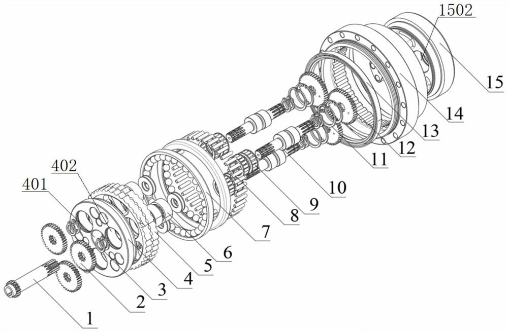
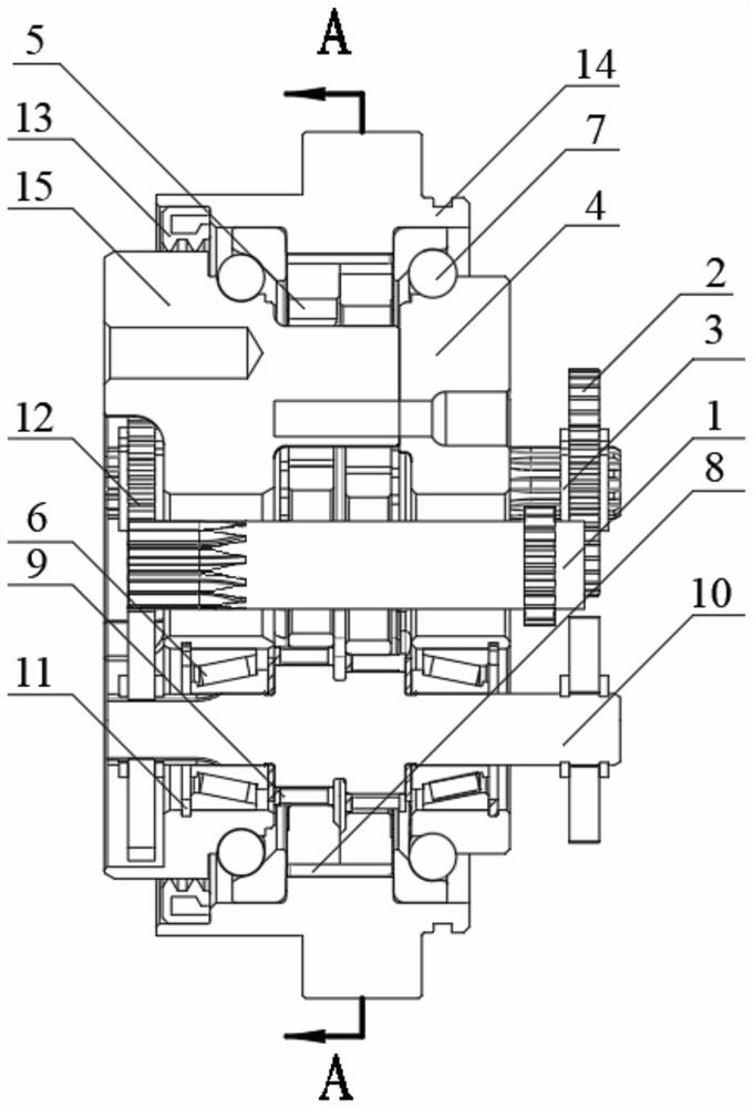
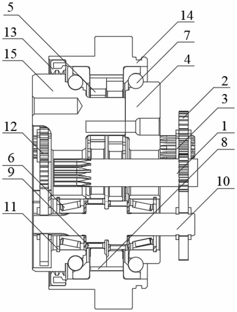
[0034] This embodiment discloses a two-speed ratio RV reducer, see Figure 1 to Figure 3 , including an input gear shaft 1, a pressure disc 4, two cycloidal wheels 5, two angular contact ball bearings 7, three crankshafts 10, and a pin gear housing 14 and an output disc 15.

[0035] The inner wall of the pin tooth housing 14 is uniformly inlaid with a plurality of pin teeth 8, forming an annular pin tooth group.

[0036] see Figure 4 , the two cycloidal wheels 5 are all meshed with the annular pin-tooth set, and the two cycloidal wheels 5 and the annular pin-tooth set form a planetary gear transmission mechanism with a tooth difference and a small tooth difference. The center of each cycloidal wheel 5 has a through hole I501. Each cycloidal wheel 5 has three bearing holes 502 evenly distributed on the circumference in the circumferential direction, and a needle bearing 9 is installed in each bearing hole 502 . A connection hole 503 is processed between two adjacent bearing...

Embodiment 2

[0048] This embodiment provides a relatively basic implementation method, a two-speed ratio RV reducer, see Figure 1 to Figure 3 , including an input gear shaft 1, a pressure disc 4, two cycloidal wheels 5, three crankshafts 10, and a pin gear housing 14 and an output disc 15.

[0049] The inner wall of the pin tooth housing 14 is uniformly inlaid with a plurality of pin teeth 8, forming an annular pin tooth group.

[0050] see Figure 4 , the two cycloidal wheels 5 are all meshed with the annular pin-tooth set, and the two cycloidal wheels 5 and the annular pin-tooth set form a planetary gear transmission mechanism with a tooth difference and a small tooth difference. The center of each cycloidal wheel 5 has a through hole I501. Each cycloidal wheel 5 has three bearing holes 502 evenly distributed on the circumference in the circumferential direction, and a needle bearing 9 is installed in each bearing hole 502 . A connection hole 503 is processed between two adjacent bea...

Embodiment 3

[0060] The main structure of this embodiment is the same as that of Embodiment 2, further including two angular contact ball bearings 7 .

[0061] The two angular contact ball bearings 7 are respectively installed on both sides of the ring-shaped needle-tooth set, and perform circumferential positioning on the ring-shaped pin-tooth set and the two cycloidal wheels 5 .


PUM


Abstract

The invention discloses a two-gear variable-speed-ratio RV speed reducer. The two-gear variable-speed-ratio RV speed reducer comprises an input gear shaft, a pressing disc, two cycloidal gears, a plurality of crankshafts, a needle tooth housing and an output disc, wherein a plurality of needle teeth are uniformly embedded in the inner wall of the needle tooth housing to form an annular needle tooth group; the two cycloidal gears are internally meshed with the annular needle tooth group; the output disc is mounted in the needle tooth housing, and a lug boss of the output disc penetrates throughconnecting holes of the two cycloidal gears; the pressing disc is mounted in the needle tooth housing, and is connected to the lug boss of the output disc through a screw; two ends of the crankshaftare respectively connected to a first-gear planetary gear and a second-gear planetary gear; when the input gear shaft moves towards the output disc, the first-gear outer teeth of the input gear shaftare meshed with the first-gear planetary gear; and when the input gear shaft moves towards the pressing disc, the second-gear outer teeth of the input gear shaft are meshed with the second-gear planetary gear. Working state switching of transmission parts of the two groups of planetary gears with different speed ratios is achieved, so that the two-gear variable-speed-ratio transmission function isachieved.

Description

technical field [0001] The invention belongs to the technical field of transmissions, and in particular relates to a two-speed ratio RV speed reducer. Background technique [0002] RV reducers are widely used in the precision transmission of industrial robot joints and the precision drive of AGV wheels. The RV reducer adopts a two-stage transmission structure design, the first stage adopts planetary gear transmission, and the second stage adopts cycloid transmission. The transmission ratio of the existing RV reducer is fixed, which cannot meet the speed ratio switching needs of industrial robots and AGVs under high and low speed conditions, which seriously restricts the performance of robots and AGVs. [0003] Therefore, there is a need in the prior art for an RV speed reducer that can solve the above problems. Contents of the invention [0004] The technical solution adopted to realize the object of the present invention is as follows, a two-speed gear ratio RV reducer,...

Claims


Application Information

Patent Timeline
IPC IPC(8): F16H3/70F16H57/029F16H57/021F16H57/023F16H57/08
CPCF16H3/70F16H57/029F16H57/021F16H57/023F16H2003/445F16H2200/0034F16H2200/2007F16H2057/085
Inventor 许立新杨博杜正柱
Owner CHONGQING UNIV
Why Eureka
Try Eureka