
Integrated inflating device

The technology of an inflatable device and gas cylinder is applied to the installation device of container structure, fluid treatment, container filling method, etc., which can solve the problems of inconvenient portability, uncontrollable pressure, slow inflation speed, etc., and achieve easy portability and transportation, stability Strong, highly reliable effect

Active Publication Date: 2021-03-12
SOUTHEAST UNIV
View PDF6 Cites 0 Cited by
  • Summary
  • Abstract
  • Description
  • Claims
  • Application Information

AI Technical Summary

Problems solved by technology

[0002] At present, the medical hemostatic airbags being developed at home and abroad need to be inflated by an inflator. At present, most of the manual inflatable inflators are inflated by manually squeezing the balloon, which is inconvenient to use and the inflation speed is slow.
Although the electric air pump can achieve a faster inflation function, the electronic air pump is bulky and inconvenient to carry
[0003] Moreover, the general inflatable device cannot automatically switch on and off following the air pressure of the inflated device, and the pressure is uncontrollable, which limits the application of hemostatic airbags and inflatable devices

Method used


Image

  • Integrated inflating device
  • Integrated inflating device
  • Integrated inflating device

Examples


Embodiment Construction

[0031] The specific embodiments of the present invention will be described below in conjunction with the accompanying drawings.

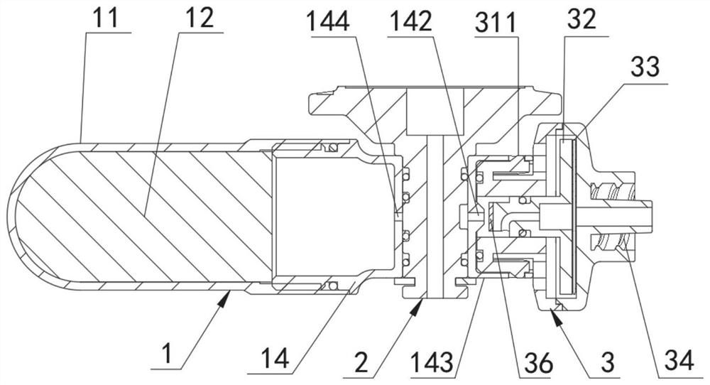
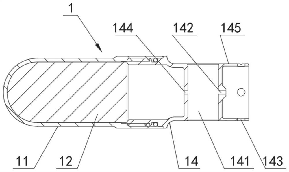
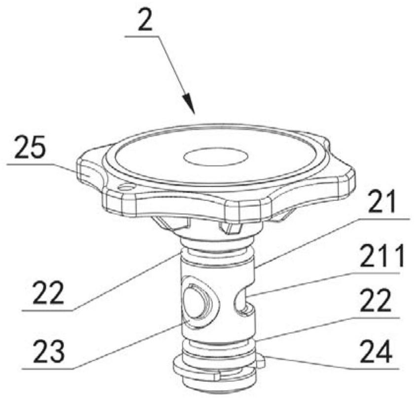
[0032] Such as figure 1 , figure 2 with Image 6 As shown, the integrated inflation device of this embodiment includes a gas cylinder assembly 1, a rotary valve assembly 2 plugged into the gas cylinder assembly 1, and a pressure reducing valve assembly 3 fixedly connected to the gas cylinder assembly 1;

[0033] Such as figure 1 with figure 2 As shown, the gas cylinder assembly 1 includes a gas cylinder body 11 for storing liquefied gas 12, and a valve seat 14 connected to the gas cylinder body 11. The valve seat 14 has a valve hole 141 for accommodating the rotary valve assembly 2 and allowing it to rotate. A communicating air passage is formed between the valve hole 141 and the relative rotating surface of the rotary valve assembly 2, and the two side walls of the valve hole 141 are correspondingly provided with air holes, and one side of th...


PUM


Abstract

The invention provides an integrated inflation device. The integrated inflation device comprises a gas cylinder assembly, a rotary valve assembly and a pressure reducing valve assembly. The gas cylinder assembly comprises a gas cylinder body and a valve seat connected to the gas cylinder body, wherein a valve hole for containing the rotary valve assembly and allowing the rotary valve assembly to rotate is formed in the valve seat, a communication gas channel is formed between the valve hole and the opposite rotating face of the rotary valve assembly, gas holes are correspondingly formed in thetwo side walls of the valve hole, the gas hole in one side is an outlet of the gas cylinder body, the gas hole in the other side communicates with a gas channel of the pressure reducing valve assembly, a sealing part is arranged on the rotary valve assembly, the pressure reducing valve assembly comprises a valve body, a valve element moving in an axial direction is arranged inside the valve body,a sealing gasket is arranged at one end of the valve element, the sealing part and the sealing gasket can be used for opening and closing gas holes in the two sides correspondingly, and therefore therapid on-off function and the pressure stabilizing function are achieved. According to the device, a gas path can be cut off or communicated according to inflation pressure, pressure stability is maintained, operation is convenient, and reliability is high.

Description

technical field [0001] The invention relates to the technical field of inflators, in particular to an integrated inflator. Background technique [0002] The medical hemostatic airbags currently being developed at home and abroad need to be inflated by an inflator. At present, most of the manual inflatable inflators are inflated by manually squeezing the balloon, which is inconvenient to use and the inflation speed is slow. Although the electric air pump can achieve a faster inflation function, the electronic air pump has a large volume and is inconvenient to carry. [0003] Moreover, the general inflatable device cannot be automatically switched on and off following the air pressure of the inflated device, and the pressure is uncontrollable, which limits the application of the hemostatic air bag and the inflatable device. [0004] Therefore need to develop a kind of fast inflation and the inflation device of steady pressure. Contents of the invention [0005] Aiming at t...

Claims


Application Information

Patent Timeline
Patent Type & Authority Applications(China)
IPC IPC(8): F17C1/00F17C7/02F17C13/04
CPCF17C1/00F17C7/02F17C13/04F17C2201/0104F17C2201/035F17C2205/0323F17C2223/035
Inventor 王兴松沈冬华田梦倩
Owner SOUTHEAST UNIV
Learn More