
Intelligent street lamp management and control device

A technology of management and control devices and smart street lamps, which can be applied to identification devices, lighting devices, lighting devices, etc., can solve the problems of single structure and function, and achieve the effect of increasing efficiency, increasing experience effect, and reducing cost.

Active Publication Date: 2021-03-12
王家驹
View PDF5 Cites 0 Cited by
  • Summary
  • Abstract
  • Description
  • Claims
  • Application Information

AI Technical Summary

Problems solved by technology

[0006] At the same time, the existing smart street lights are equipped with advertising screens on the light poles, but the existing advertising screens are usually set at a higher position in the middle of the light poles, which are only convenient for pedestrians to watch, and the structure and function are single.

Method used


Image

  • Intelligent street lamp management and control device
  • Intelligent street lamp management and control device
  • Intelligent street lamp management and control device

Examples


Embodiment 1

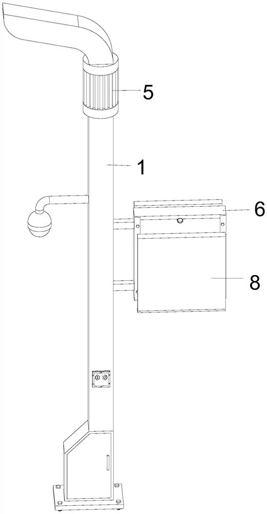
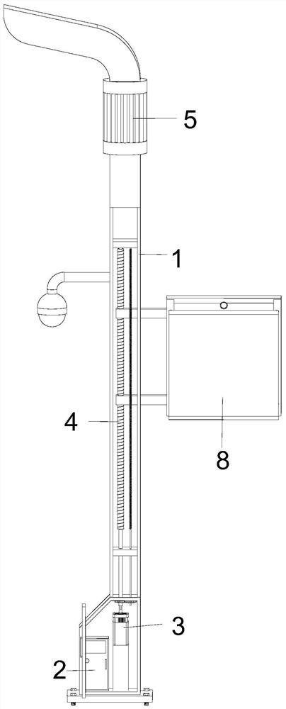
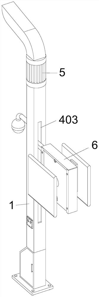
[0032] Please refer to Figure 1-4, a smart street lamp control device, including a light pole 1, the light pole 1 is set in a vertical rectangular structure with a hollow interior, a power distribution cabinet 2 is installed inside the bottom of the light pole 1, and the interior of the light pole 1 A servo motor 3 is provided on the right side of the power distribution cabinet 2, a lifting assembly 4 is provided above the servo motor 3, a monitoring device is provided in the middle of the left side of the light pole 1, a signal base station 5 is provided on the outer wall of the top of the light pole 1, and a signal base station 5 is provided on the outer wall of the light pole 1. 1. A support box 6 is provided in the middle of the right side, and a drive assembly 7 is provided inside the support box 6. Two touch screens 8 are provided on the front and rear sides of the support box 6 in a symmetrical structure.

[0033] The lifting assembly 4 includes a threaded rod A401, whic...

Embodiment 2

[0037] Please refer to Figures 5-8, the difference in the basis of Embodiment 1 is that the middle part of the front and rear ends of the support box 6 is fixed with a swivel seat A601, and the inner end of the touch screen 8 is provided with a position relative to the swivel seat A601. The swivel seat B801, the swivel seat A601 is rotatably connected with the swivel seat B801.

[0038] The driving assembly 7 includes two image processors 701, which are symmetrically arranged in the top of the support box 6. The imaging probe at the outer end of the image processor 701 extends through the outer wall of the support box 6 to its outside.

[0039] The driving assembly 7 also includes two limit sleeve rods 702, the two limit sleeve rods 702 are front and rear symmetrical structures and are fixed with the outer wall of the support box 6 relative to the position below the rotating seat A601, and the inside of the limit sleeve rods 702 is provided with a slide The rod 703, the outer ...


PUM


Abstract

The invention discloses an intelligent street lamp management and control device, and belongs to the technical field of intelligent street lamps. The intelligent street lamp management and control device comprises a lamp post which is of a vertical rectangular structure with a hollow interior. A power distribution cabinet is arranged in the bottom end of the lamp post, a servo motor is arranged atthe position, corresponding to the right side of the power distribution cabinet, in the lamp post, and a lifting assembly is arranged above the servo motor. A monitoring device is arranged in the middle of the left side of the lamp post, and a signal base station is arranged on the outer wall of the top end of the lamp post. A supporting box is arranged in the middle of the right side of the lamppost, a driving assembly is arranged in the supporting box, and two touch screens are symmetrically arranged on the front side and the rear side of the supporting box. According to the intelligent street lamp management and control device, the servo motor is arranged at the bottom end of the lamp post, ascending and descending of the touch screens are controlled through starting of the motor, andmeanwhile, automatic inclination is achieved in the descending process of the touch screens, so that citizens can control the touch screens conveniently.

Description

technical field [0001] The present invention relates to the technical field of smart street lights, and more specifically, to a control device for smart street lights. Background technique [0002] Smart street lights refer to street lights that realize remote centralized control and management of street lights by applying advanced, efficient, and reliable power line carrier communication technology and wireless GPRS / CDMA communication technology. Smart street lights can automatically adjust brightness according to traffic flow and remote lighting control. , fault active alarm, lighting and cable anti-theft, remote meter reading and other functions can greatly save power resources, improve public lighting management level, and save maintenance costs. [0003] At the same time, the existing smart street lights are equipped with advertising screens on the light poles to disseminate information. However, the existing advertising screens are usually located at a higher position ...

Claims


Application Information

Patent Timeline
IPC IPC(8): F21V33/00G09F9/30G09F23/00F21W131/103
CPCF21V33/00G09F9/30G09F23/00F21W2131/103Y02B20/72
Inventor 王家驹张小平
Owner 王家驹
Learn More