Pressure transmitter based on laser resistance-adjusting temperature compensation technology
A technology of temperature compensation and laser resistance adjustment, which is applied in the direction of fluid pressure measurement, fluid pressure measurement, and instruments using liquid as a pressure-sensitive medium, and can solve problems such as inaccurate pressure sensing values of pressure sensors and errors in pressure measurement
- Summary
- Abstract
- Description
- Claims
- Application Information
AI Technical Summary
Problems solved by technology
Method used
Image
Examples
Embodiment 1
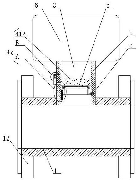
[0025] Embodiment 1, with reference to Figure 1-4 , the pressure transmitter based on laser trimmed resistance temperature compensation technology includes a fixed pipe 1, the top of the fixed pipe 1 is fixedly connected with a connecting pipe 2, both ends of the fixed pipe 1 are connected with flanges 12, and the connecting pipe 2 A pressure sensor 3 is fixedly connected inside, the connecting pipe 2 is connected with an isolation diaphragm 5 through a connecting mechanism 4, the end of the connecting pipe 2 far away from the fixed pipe 1 is connected with a controller 6, and the connecting pipe 2 is filled with silicone oil;
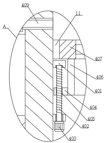
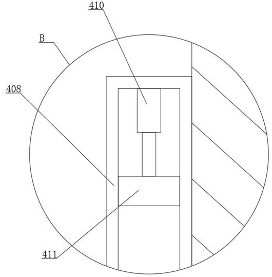
[0026] Connection mechanism 4 comprises two supporting blocks 401, threaded rod 402, driving motor 403, moving block 404, threaded hole 405, fixed cylinder 406, fixed ring 407, oil tank 408, oil pipe 409, electric control telescoping rod 410, piston 411 and temperature Inductor 412, two support blocks 401 are fixedly connected on the inner tube wall o...
Embodiment 2
[0027] Embodiment 2 is on the basis of embodiment 1 such as Figure 4 As shown, the outer wall of its fixed cylinder 406 away from the moving block 404 is fixedly connected with a T-shaped slider 7, and the inner tube wall of the connecting pipe 2 corresponding to the position of the T-shaped slider 7 is provided with a T-shaped chute 8, T Type slide block 7 is slidably connected in T-shaped chute 8, makes fixed cylinder 4016 more stable, is difficult for shaking.
Embodiment 3
[0028] Embodiment 3 is such as on the basis of embodiment 2 Figure 4 As shown, the end of its T-shaped slider 7 close to the bottom of the T-shaped chute 8 is provided with a ball groove 9, and the ball groove 9 is rollingly connected with a ball 10, and the end of the ball 10 away from the groove bottom of the ball groove 9 passes through the ball groove. The notch of 9 is also rollingly connected to the bottom of the T-shaped chute 8, so that the T-shaped slide block 7 moves more smoothly and is not easy to block.
PUM
 Abstract
Description
Claims
Application Information
 - R&D
- Intellectual Property
- Life Sciences
- Materials
- Tech Scout
- Unparalleled Data Quality
- Higher Quality Content
- 60% Fewer Hallucinations
Browse by: Latest US Patents, China's latest patents, Technical Efficacy Thesaurus, Application Domain, Technology Topic, Popular Technical Reports.
© 2025 PatSnap. All rights reserved.Legal|Privacy policy|Modern Slavery Act Transparency Statement|Sitemap|About US| Contact US: help@patsnap.com


