
Split turbofan engine nacelle force measurement test device with power simulation and force measurement test method

A technology of turbofan engine and force measurement test, which is applied in gas turbine engine test, jet engine test, aerodynamic test and other directions, can solve the problems of difficulty in deduction and difficult to accurately evaluate the influence of aerodynamic characteristics of engine nacelles, and achieve accurate The effect of measurement

Active Publication Date: 2021-03-12
INST OF HIGH SPEED AERODYNAMICS OF CHINA AERODYNAMICS RES & DEV CENT
View PDF9 Cites 12 Cited by
  • Summary
  • Abstract
  • Description
  • Claims
  • Application Information

AI Technical Summary

Problems solved by technology

[0004] The air intake flow coefficient obtained by using a simple flow adjustment device is about 0.4 to 0.7, which is lower than the nacelle flow coefficient of 0.6 to 2.0 under flight conditions. It is difficult to accurately evaluate the influence of air intake and exhaust on the aerodynamic characteristics of the engine nacelle under flight conditions.
In addition, the conventional ventilation test nacelle is connected to the balance through a support plate (as described in the patent authorization announcement number CN207717325U), and the force measured by the balance includes the force of the nacelle support, which is difficult to deduct

Method used


Image

  • Split turbofan engine nacelle force measurement test device with power simulation and force measurement test method
  • Split turbofan engine nacelle force measurement test device with power simulation and force measurement test method
  • Split turbofan engine nacelle force measurement test device with power simulation and force measurement test method

Examples


Embodiment Construction

[0046] The present invention will be further described in detail below in conjunction with the accompanying drawings, so that those skilled in the art can implement it with reference to the description.

[0047] It should be understood that terms such as "having", "comprising" and "including" as used herein do not entail the presence or addition of one or more other elements or combinations thereof.

[0048] It should be noted that in the description of the present invention, the orientation or positional relationship indicated by the term is based on the orientation or positional relationship shown in the drawings, which is only for the convenience of describing the present invention and simplifying the description, and does not indicate or imply No device or element must have a specific orientation, be constructed, and operate in a specific orientation and therefore should not be construed as limiting the invention. In addition, the terms "first" and "second" are used for de...


PUM


Abstract

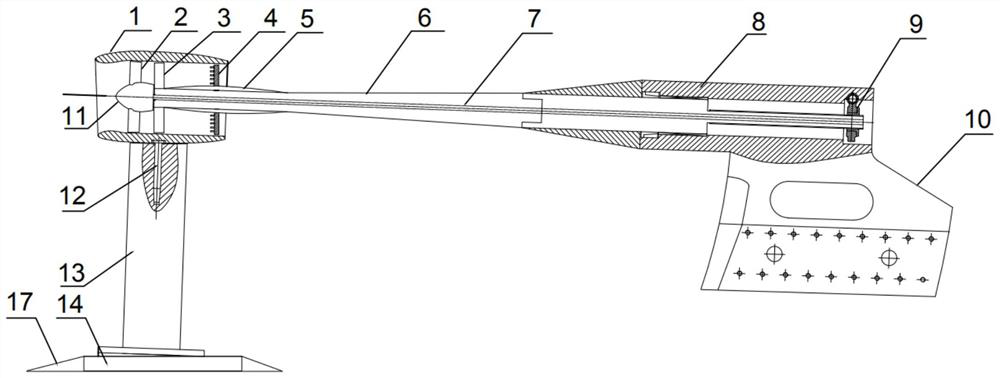
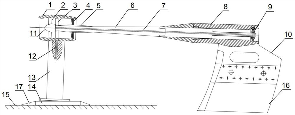
The invention discloses a split turbofan engine nacelle force measurement test device with power simulation and a force measurement test method. The device comprises a front end supporting mechanism,a rod-type balance, a propeller hub, a supporting rod, a pressure measuring rake andouter culvert guide vanes; one end of the rod-type balance is connected with the front-end supporting mechanism, theother end of the rod-type balance is connected with a nacelle, and a gap is formed between the nacelle and the front-end supporting mechanism; the propeller hub is mounted in the nacelle, and a fan blade disc is mounted on the propeller hub; a transmission shaft is arranged in the supporting rod, one end of the transmission shaft is fixedly connected with the propeller hub, a turbine is installedat the other end of the transmission shaft, the supporting rod is connected with a turbine box, and the turbine is located in the turbine box which is arranged on the rear-end supporting mechanism; the pressure measuring rake is mounted on the supporting rod; and the outer culvert guide vanes are mounted at the end parts of the supporting rods. Independent nacelle inlet air flow can be simulatedby regulating and controlling the rotating speed of the fan, accurate measurement of model aerodynamic force under the influence of simulated nacelle air inlet and exhaust is achieved, and the obtained test data has important value for guiding design and optimization of the turbofan engine nacelle and the whole airplane.

Description

technical field [0001] The invention belongs to the field of power measurement of a turbofan engine and a turbofan engine nacelle model, and in particular relates to a split-type turbofan engine nacelle force-measuring test device and a force-measuring test method with power simulation. Background technique [0002] The development of advanced civil aircraft increasingly emphasizes economy, safety, comfort and environmental protection, and puts forward higher and higher requirements for engines, aerodynamic layout and materials. In order to achieve excellent economy, civil aircraft generally use high bypass ratio turbofan engines to significantly reduce engine fuel consumption. There are two main installation methods for high bypass ratio engines: underwing or outside the fuselage. This kind of engine has a large size and a very rough shape, and needs to be rectified by a nacelle with a smooth shape to reduce the flight resistance of the whole machine. Therefore, in order ...

Claims


Application Information

Patent Timeline
Patent Type & Authority Applications(China)
IPC IPC(8): G01M15/14G01M9/06
CPCG01M9/065G01M15/14
Inventor 郭秋亭熊能范长海林俊杜宁潘华烨王超陶洋张诣杨海滨贾晓东高荣钊刘光远
Owner INST OF HIGH SPEED AERODYNAMICS OF CHINA AERODYNAMICS RES & DEV CENT
Learn More