Shielding coating device for compact arrangement small reactor with large expansion difference

A cladding device and small-scale reactor technology, which is applied in the field of nuclear power, can solve the problems of narrow gaps between main equipment, small size of pressure vessels, and difficult implementation, and achieve the effects of improved shielding effect, simplified structure, and guaranteed integrity and reliability

Pending Publication Date: 2021-03-12
CHINA NUCLEAR POWER TECH RES INST CO LTD +2
View PDF0 Cites 0 Cited by
  • Summary
  • Abstract
  • Description
  • Claims
  • Application Information

AI Technical Summary

Problems solved by technology

The shielding scheme of the existing small reactor structure is not perfect, and there are problems such as shielding structure design and implementation difficulty
[0003] In addition, the module is a rectangular plate, which needs to be mechanically locked by screws, and is arranged in the shielding surface. The shielding module is covered on one side, and the shielding material is MDF. The high temperature at the stack cannot meet the sealing requirements of the shielding material coating, and cannot meet the installation and positioning requirements in such a small space as the stack pit, and the MDF cannot meet the neutron shielding requirements
[0004] At the same time, the existing small reactors cannot be used in environments where the distance between the main equipment such as the main pump and steam generator is narrow, and the core and external shielding requirements are also higher. For example, the existing small reactors usually use integrated or double-layer The size of the reactor pressure vessel is small, the inner wall of the RPV is closer to the core, and the neutrons reflected by the core are likely to cause radiation damage to the inner wall of the reactor pressure vessel; the gap between the main equipment is narrow, and the distance between the main equipment and the reactor The core is relatively close, and the existing commonly used shielding structure can no longer adapt to the installation of the above structure

Method used


Image

  • Shielding coating device for compact arrangement small reactor with large expansion difference
  • Shielding coating device for compact arrangement small reactor with large expansion difference

Examples


Embodiment Construction

[0018] The following will clearly and completely describe the technical solutions in the embodiments of the present invention with reference to the accompanying drawings in the embodiments of the present invention. Obviously, the described embodiments are only some, not all, embodiments of the present invention. Based on the embodiments of the present invention, all other embodiments obtained by persons of ordinary skill in the art without creative efforts fall within the protection scope of the present invention.

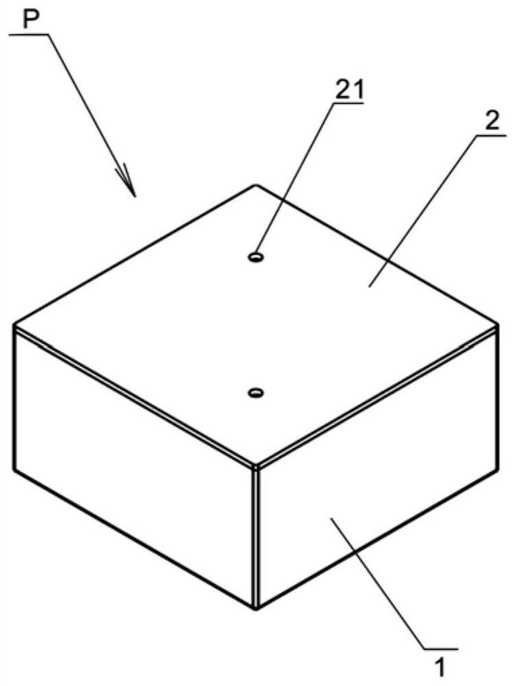
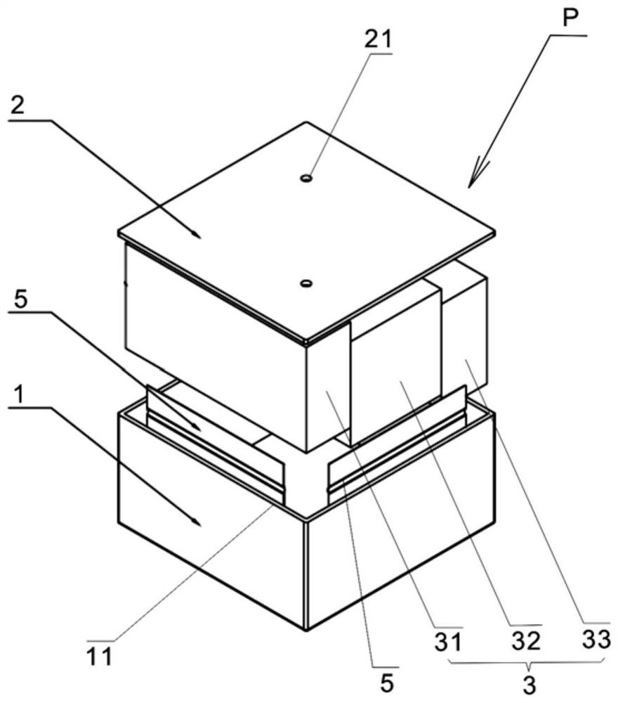
[0019] see Figure 1-Figure 2 Shown is Embodiment 1 of the present invention for compactly arranging a shielding and covering device for a small stack with a large expansion difference.

[0020] The structure of the shielding and covering device P for compactly arranging small-sized shielding bodies in this embodiment includes: a cladding 1 with an opening at one end, and the cladding 1 installed inside the cladding 1 is made of one material or made of multiple mat...


PUM


Abstract

The invention discloses a shielding coating device for a large expansion difference of a compactly-arranged small reactor. The shielding coating device comprises a coating shell with an opening formedin one end; a shielding body which is arranged in the cladding and is formed by combining one material or a plurality of materials; a cover plate, which is sealed at the open end of the cladding, wherein an elastic piece is arranged between the periphery of the shielding body and the cladding. According to the shielding coating device for the large expansion difference of the compactly-arranged small reactor, thermal expansion of the shielding body can be released when the thermal expansion difference value of the shielding body and the cladding is large at the design temperature, so that theintegrity and the reliability of the shielding coating device are guaranteed; in addition, the structure is simplified and shielding effect is also improved.

Description

technical field [0001] The invention relates to the field of nuclear power, in particular to a shielding and cladding device for compactly arranging small stacks with large expansion differences. Background technique [0002] For small reactors, especially small reactors at sea, in order to meet the requirements of the marine environment and the limited layout space of the cabin, the main equipment of the primary circuit nuclear island usually adopts a compact layout, such as integrated design, short pipe connection, etc. The shielding scheme of the existing small reactor structure is not perfect, and there are problems such as shielding structure design and implementation difficulty. [0003] In addition, the module is a rectangular plate, which needs to be mechanically locked by screws, and is arranged in the shielding surface. The shielding module is covered on one side, and the shielding material is MDF. The high temperature at the stack cannot meet the sealing requirem...

Claims


Application Information

Patent Timeline
IPC IPC(8): G21C11/04G21C11/02
CPCG21C11/04G21C11/024Y02E30/30
Inventor 彭祥阳魏旭东邓玺侯硕奚琛倪亮丁祥彬韩万富路广遥刘青松唐叔建周建明陈帅王祎玞
Owner CHINA NUCLEAR POWER TECH RES INST CO LTD
Why Eureka
Try Eureka