Electric power safety object connection ground wire clamping device

A technology of electric safety and clamping device, which is applied in the direction of conductive connection, electrical component connection, circuit, etc., can solve the problems of poor stability and falling off, and achieve the effect of stable clamping, convenient disassembly and assembly, and adjustable clamping range

Inactive Publication Date: 2021-03-12
郭连坤
View PDF1 Cites 0 Cited by
  • Summary
  • Abstract
  • Description
  • Claims
  • Application Information

AI Technical Summary

Problems solved by technology

[0006] The purpose of the present invention is to provide a ground wire clamping device for electric safety object connection, which has the advantages of adjustable clamping range, stable clamping and convenient disassembly, and solves the problem of existing wire connection devices, whi

Method used


Image

  • Electric power safety object connection ground wire clamping device
  • Electric power safety object connection ground wire clamping device
  • Electric power safety object connection ground wire clamping device

Examples


Example Embodiment

[0036] Example 1:

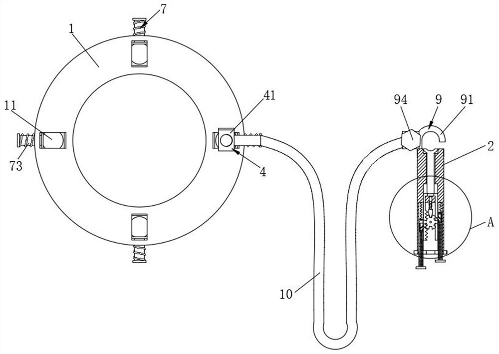
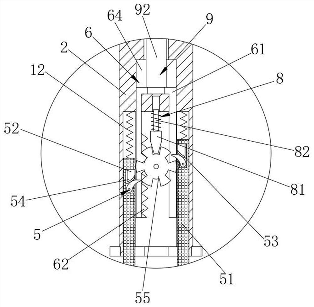
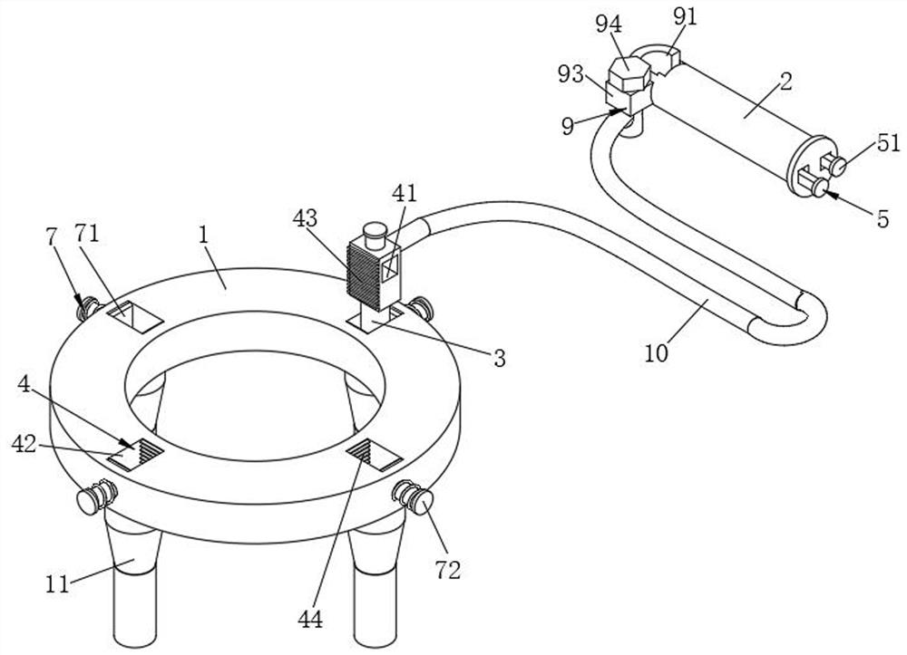
[0037] see Figure 1-7 , the present invention provides a technical solution: an electric safety object connection ground wire clamping device, comprising a mounting plate 1 and a pipe fitting 2, the top of the mounting plate 1 is provided with a ground plug 3, and the top of the mounting plate 1 is annularly provided with four There are two installation mechanisms 4. Pushing mechanisms 5 are provided on both sides of the inner cavity of the pipe fitting 2. The pushing mechanism 5 includes a pushing bar 51 slidably connected to both sides of the inner cavity of the pipe fitting 2. The rear side of the top of the pushing bar 51 is provided with an L-shaped groove. 52, the bottom of the inner cavity of the L-shaped groove 52 is rotatably connected with an arc-shaped push block 54, the center of the bottom of the inner cavity of the pipe fitting 2 is provided with a limited rotation member 55, and the inner cavity of the pipe fitting 2 is provided with a propu...

Example Embodiment

[0042] Embodiment 2:

[0043] see Figure 1-7 , the present invention provides a technical solution: an electric safety object connection ground wire clamping device, comprising a mounting plate 1 and a pipe fitting 2, the top of the mounting plate 1 is provided with a ground plug 3, and the top of the mounting plate 1 is annularly provided with four There are two installation mechanisms 4. Pushing mechanisms 5 are provided on both sides of the inner cavity of the pipe fitting 2. The pushing mechanism 5 includes a pushing bar 51 slidably connected to both sides of the inner cavity of the pipe fitting 2. The rear side of the top of the pushing bar 51 is provided with an L-shaped groove. 52, the bottom of the inner cavity of the L-shaped groove 52 is rotatably connected with an arc-shaped push block 54, the center of the bottom of the inner cavity of the pipe fitting 2 is provided with a limited rotation member 55, and the inner cavity of the pipe fitting 2 is provided with a pr...


PUM


Abstract

The invention discloses an electric power safety object connection ground wire clamping device which comprises a mounting plate and a pipe fitting, a ground plug is arranged at the top of the mountingplate in a penetrating mode, four mounting mechanisms are annularly arranged at the top of the mounting plate, and pushing mechanisms are arranged on the two sides of an inner cavity of the pipe fitting. And each pushing mechanism comprises pushing strips slidably connected to the two sides of an inner cavity of the pipe fitting, L-shaped grooves are formed in the rear sides of the tops of the pushing strips, and arc-shaped pushing blocks are rotatably connected to the bottoms of inner cavities of the L-shaped grooves. Through the arrangement of the connecting mechanism and the mounting mechanisms, the two ends of the conductive wire are connected with the pipe fitting and the mounting plates correspondingly; Then, through cooperative use of the pushing mechanisms and the feeding mechanism, the pipe fitting clamps the wiring end of the ground wire of the Internet of Things equipment, and through cooperative use of the mounting mechanisms and the extrusion mechanism, the ground plug isstably inserted into the ground, so that the purposes of adjustable clamping range, stable clamping and convenient disassembly and assembly can be achieved.

Description

technical field [0001] The invention relates to the technical field of electric equipment, in particular to a ground wire clamping device connected to electric safety objects. Background technique [0002] The ground wire is the wire directly connected to the earth, and it can also be called a safety return line. When it is in danger, it will directly transfer the high voltage to the earth. With a certain amount of static electricity, electric shock accidents may occur in severe cases. In order to avoid accidents, a wire can be connected to the metal shell of the electrical appliance, and the other end of the wire should be connected to the ground. Once the electrical leakage occurs, the grounding wire will bring static electricity into the electrical appliance. In addition, when electrical maintenance personnel use an electric soldering iron to weld the circuit, sometimes the integrated circuit in the electrical appliance will be broken down due to the electrification of th...

Claims


Application Information

Patent Timeline
IPC IPC(8): H01R11/11H01R11/14H01R4/66
CPCH01R4/66H01R11/11H01R11/14
Inventor 郭连坤
Owner 郭连坤
Why Eureka
Try Eureka