Ammunition clamping device

A clamping device and ammunition technology, which is applied to ammunition, weapon accessories, offensive equipment, etc., can solve the problems of high rigidity and easy slippage of the clamping jaw, and achieve the effects of large clamping force, reasonable layout and adjustable clamping range.

Active Publication Date: 2020-03-24
SHENYANG INST OF AUTOMATION - CHINESE ACAD OF SCI
View PDF7 Cites 1 Cited by
  • Summary
  • Abstract
  • Description
  • Claims
  • Application Information

AI Technical Summary

Problems solved by technology

The power of existing clamping devices is generally divided into pneumatic, hydraulic or electric methods. The clamping force of the pneumatic method is small, and a large hydraulic system is required for the hydraulic method; The claws are rigid and easy to slip

Method used


Image

  • Ammunition clamping device
  • Ammunition clamping device
  • Ammunition clamping device

Examples


Embodiment 1

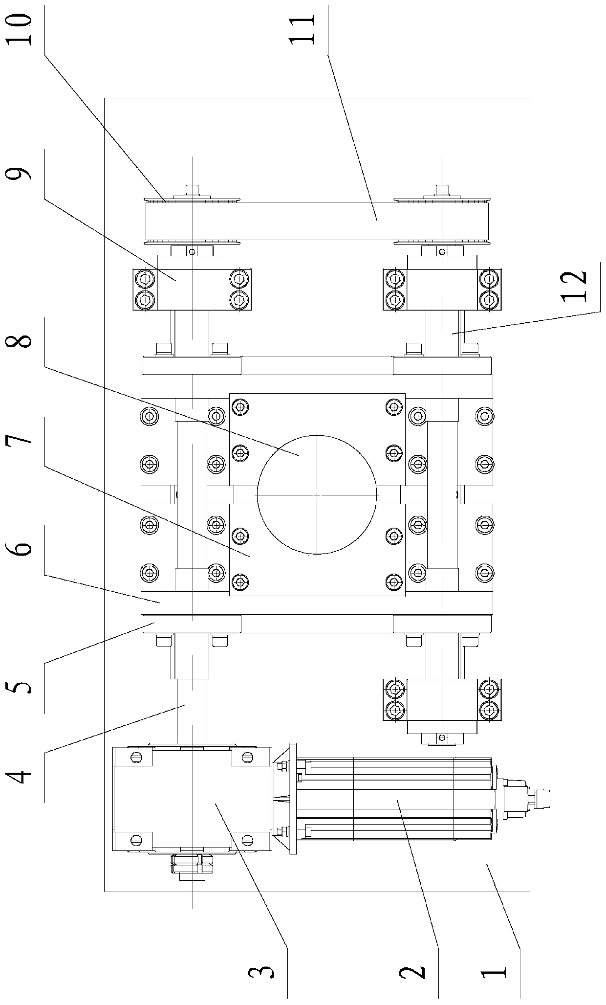
[0024] Such as figure 1 , figure 2 As shown, the present invention includes installation base 1, power source, shaft A4, nut 5, jaw mounting plate 6, jaw 7, rotary support 9, transmission mechanism, shaft B12 and guide mechanism, wherein shaft A4 and shaft B12 are respectively Installed on the installation base 1 through the rotary support 9, the axis A4 and the rotary support 9 and the shaft B12 and the rotary support 9 are connected in rotation, and the axis A and the axis B are parallel to each other; one end of the axis A4 / axis B12 is connected to the installation The output end of the power source on the installation base 1 is connected, and the other end is connected with the shaft B12 / axis A4 through the transmission mechanism; the power source drives the shaft A4 / axis B12 to rotate, and drives the shaft B12 / axis A4 to rotate synchronously and in the same direction through the transmission mechanism. The power source of this embodiment includes a motor 2 and a reducer...

Embodiment 2

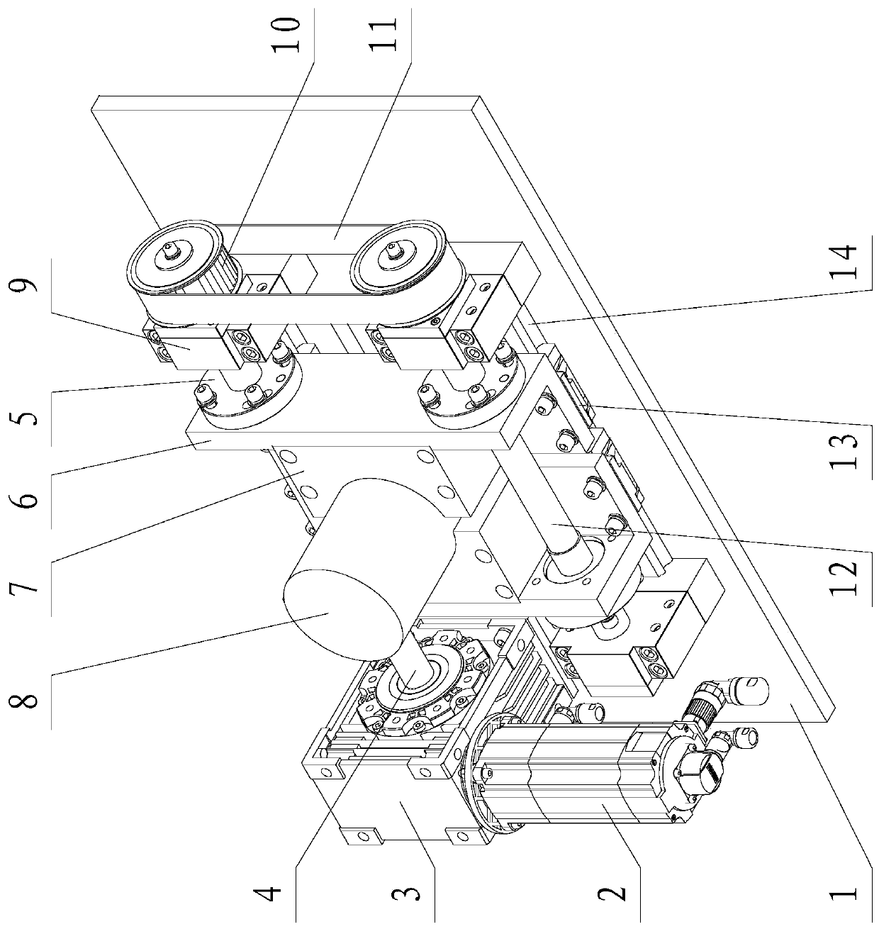
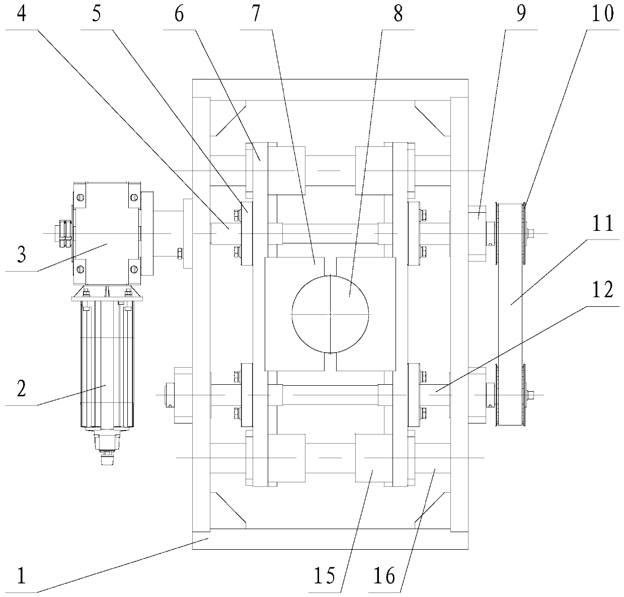
[0028] Such as image 3 , Figure 4 As shown, the difference between this embodiment and Embodiment 1 is that the installation base 1 of this embodiment is a square frame structure, and the rotary support 9, the nut 5, the jaw mounting plate 6, and the jaws 7 are respectively installed on the two sides of the frame. and the guiding mechanism are all located in the square frame, and the transmission mechanism and the power source are all located outside the square frame. The guiding mechanism of this embodiment includes a linear bearing 15 and an optical axis 16, the optical axis 16 is installed on the installation base 1, and each jaw mounting plate 6 is connected with a linear bearing 15 (there are four linear bearings 15 in total). The jaw mounting plate 6 is slidably connected with the optical axis 16 through a linear bearing 15 . In this embodiment, one optical axis 16 is provided above the axis A4 and below the axis B12 respectively, and the two optical axes 16 are para...


PUM


Abstract

The invention relates to an ammunition clamping device. A shaft A and a shaft B are installed on an installation base body through a rotary support. One end of the shaft A / the shaft B is connected with the output end of a power source installed on the installation base body, and the other end of the shaft A / the shaft B is connected with the shaft B / the shaft A through a transmission mechanism. Threaded sections are manufactured at the two ends of the shaft A and the two ends of the shaft B correspondingly. The threaded sections of the two ends of the shaft A are identical in screw pitch and opposite in rotation direction. The threaded sections of the two ends of the shaft B are identical in screw pitch and opposite in rotation direction, and the rotation directions of the threaded sectionslocated at the same ends of the shaft A and the shaft B are identical. Each threaded section on the shaft A and the shaft B is in threaded connection with a nut. Screw pairs are formed between the nuts and the threaded sections on the shaft A and the shaft B. Clamping jaw installation plates are connected between the nuts in threaded connection with the same threaded sections on the shaft A and the shaft B. The faces, which face each other, of the two clamping jaw installation plates are both provided with clamping jaws. The ammunition clamping device is compact in structure and reasonable inlayout, automatic clamping can be achieved, the clamping force is high, self-locking can be achieved, the two clamping jaws move synchronously, the centering property is high, the clamping range is adjustable, and the adaptability is high.

Description

technical field [0001] The invention belongs to the field of missile assembly, in particular to an ammunition clamping device. Background technique [0002] During the assembly process of artillery shells and small-caliber missiles, cylindrical components such as seeker, warhead, control cabin, and engine often encounter processes such as bonding, tightening, and spot riveting. A clamping device is needed to clamp the cylindrical components . The power of existing clamping devices is generally divided into pneumatic, hydraulic or electric methods. The clamping force of the pneumatic method is small, and a large hydraulic system is required for the hydraulic method; The claws are rigid and easy to slip. With the continuous improvement of domestic automation transformation requirements in the production and assembly of shells and small-caliber missiles, there is an urgent need for a general-purpose cylindrical clamping device with a large clamping force. Contents of the in...

Claims


Application Information

Patent Timeline
Patent Type & Authority Applications(China)
IPC IPC(8): F42B33/00
CPCF42B33/001
Inventor 郭爱波白鑫林王军义徐志刚张延利李峰窦宏印
Owner SHENYANG INST OF AUTOMATION - CHINESE ACAD OF SCI
Why Eureka
Try Eureka