Usage method of stringing construction device for power transmission technology

A technology for construction equipment and overhead transmission lines, which is applied to overhead lines/cable equipment, etc., can solve the problems of increased safety risks in the construction of overhead lines, easy exhaustion of construction personnel, and increased labor intensity of construction personnel.

Inactive Publication Date: 2021-03-12
秦瀚涛
View PDF0 Cites 1 Cited by
  • Summary
  • Abstract
  • Description
  • Claims
  • Application Information

AI Technical Summary

Problems solved by technology

[0003] There is an existing frame-type flying car, which drives the friction wheel by manpower. Since the manpower drive of the friction wheel increases the labor intensity of the construction workers, the construction workers are prone to exhaustion. The safety risk is increased, so we propose a method of using auxiliary equipment for wire construction for power transmission technology

Method used


Image

  • Usage method of stringing construction device for power transmission technology
  • Usage method of stringing construction device for power transmission technology
  • Usage method of stringing construction device for power transmission technology

Examples


Embodiment 1

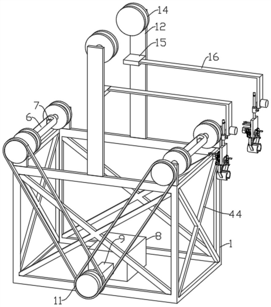
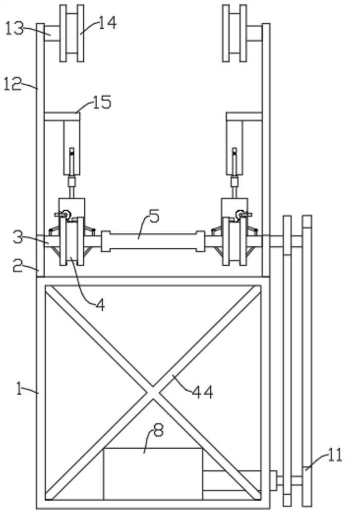
[0036] refer to Figure 1-7 , a method for using wire construction equipment for power transmission technology, comprising the following steps:

[0037] S1: Provide a wire construction auxiliary equipment for power transmission technology. The wire construction auxiliary equipment for power transmission technology includes a housing 1, in which:

[0038] The four corners of the top of the casing 1 are fixedly equipped with side plates 2, and the opposite sides of the side plates 2 can be rotatably installed with driving wheel shafts 3. There is an interval between the two driving wheel shafts 3 on the same side. Both drive wheels 4 are fixedly installed, and a cross bar 5 is provided between the two drive wheel shafts 3 on the same side, and a rectangular opening 6 is provided on the cross bar 5, and bolts 7 are arranged on both sides of the rectangular opening 6, The bolt 7 runs through the cross bar 5 and is threadedly connected to the drive wheel shaft 3. A box body 8 is f...

Embodiment 2

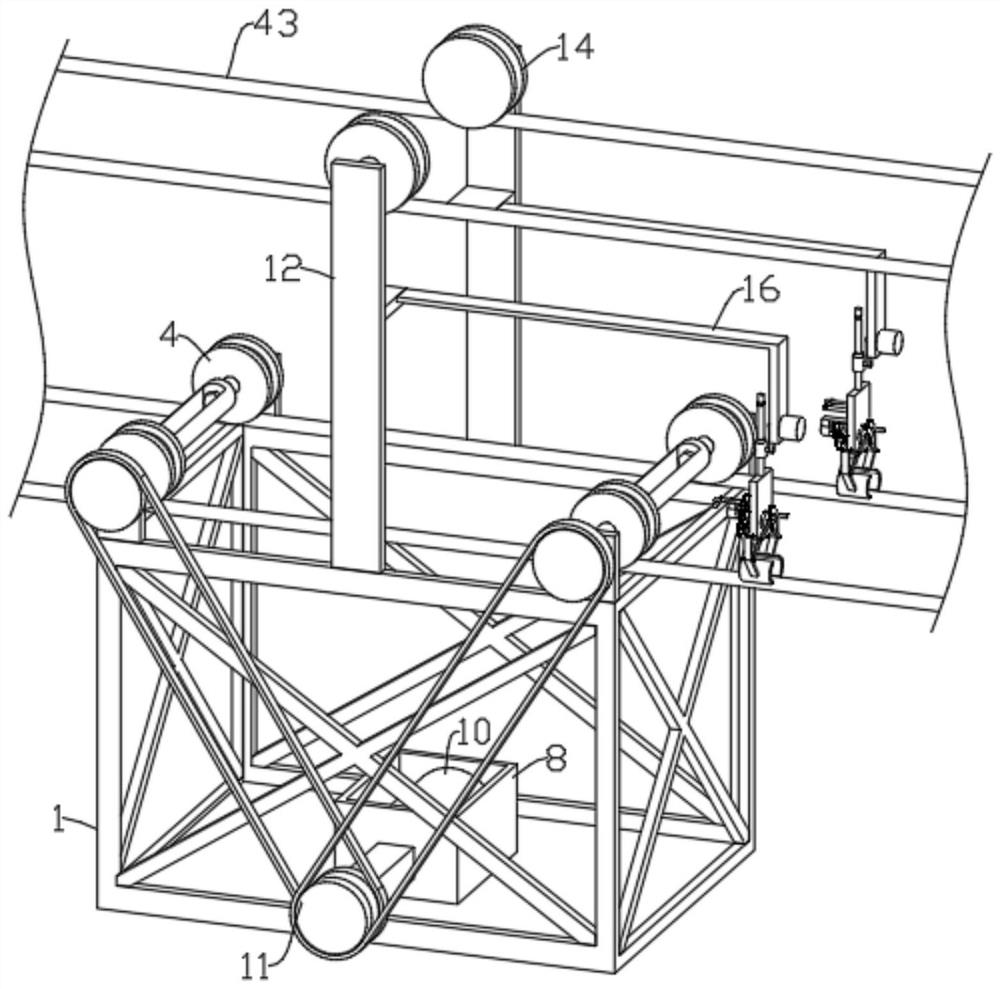
[0046] When the device is used in an environment with high humidity or after rainy weather, since water droplets remain on the wire 43 of the external overhead transmission line, the friction between the driving wheel 4 and the wire 43 in Embodiment 1 is reduced. On the one hand It will affect the driving performance of the device, and on the other hand, it will increase the braking distance of the device.

[0047] refer to Figure 1-7 , as another preferred embodiment of the present invention, the difference from Embodiment 1 is that support blocks 15 are fixedly installed on opposite sides of the two vertical plates 12, and a cleaning mechanism is provided on the two support blocks 15, and the cleaning mechanism includes L-shaped support plate 16, one end of the L-shaped support plate 16 is fixedly installed on one side of the support block 15, the lower end of the L-shaped support plate 16 is provided with a carrier plate 17, and the carrier plate 17 is provided with two gr...


PUM


Abstract

The invention relates to a stringing construction device, in particular to a usage method of the stringing construction device for a power transmission technology. The method comprises the following steps of S1, providing a stringing construction auxiliary device for the power transmission technology, wherein the stringing construction auxiliary device for the power transmission technology comprises a basket body, side plates are fixedly mounted at the four corners of the top of the basket body, and driving wheel shafts are rotatably mounted at the opposite sides of the side plates; S2, dismounting bolts and taking out a cross rod, and mounting the stringing construction auxiliary device for the power transmission technology on a wire of an external overhead power transmission line; S3, starting a driving motor, and enabling the stringing construction auxiliary device for the power transmission technology to run along the wire. By arranging the basket body, the side plates, the drivingwheel shafts, driving wheels, the driving motor and a chain wheel and chain transmission mechanism, the chain wheel and chain transmission mechanism drives the driving wheel shafts at the two ends torotate, and therefore an aerodyne can run on the wire without being driven by manpower.

Description

technical field [0001] The invention relates to stringing construction equipment, in particular to a method for using the stringing construction equipment for power transmission technology. Background technique [0002] There is a kind of overhead wire construction auxiliary equipment for power transmission technology-flying car. The flying car uses the wires of the overhead transmission line as the driving track, and the friction wheel is driven by manpower or power device. The friction between the friction wheel and the wire makes the flying car on the wire. Driving, the speeding car can be used in occasions such as wiring construction and line maintenance in power transmission projects. [0003] There is an existing frame-type flying car, which drives the friction wheel by human power. Because the human-driven friction wheel increases the labor intensity of the construction workers, the construction workers are prone to exhaustion. Therefore, we propose a method of using...

Claims


Application Information

Patent Timeline
Patent Type & Authority Applications(China)
IPC IPC(8): H02G1/04
CPCH02G1/04
Inventor 不公告发明人
Owner 秦瀚涛
Why Eureka
Try Eureka