Electric heavy-duty vehicle wheel rim driving assembly

A technology of wheel drive and motor drive, which is applied in the direction of electric components, vehicle components, and control/drive circuits, etc. It can solve the problems of low integration and high cost of the motor system, and achieve cost saving, layout and high integration. Effect

Pending Publication Date: 2019-09-17
深圳数翔科技有限公司
View PDF1 Cites 1 Cited by
  • Summary
  • Abstract
  • Description
  • Claims
  • Application Information

AI Technical Summary

Problems solved by technology

[0004] The purpose of the present invention is to propose an electric heavy-duty vehicle wheel drive assem

Method used


Image

  • Electric heavy-duty vehicle wheel rim driving assembly
  • Electric heavy-duty vehicle wheel rim driving assembly
  • Electric heavy-duty vehicle wheel rim driving assembly

Examples


specific Embodiment approach 1

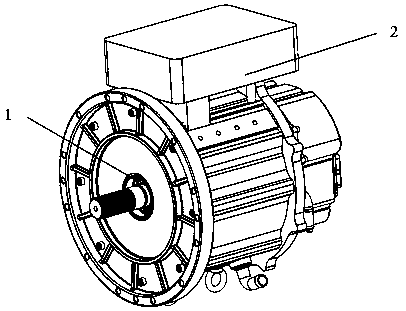
[0023] The wheel drive assembly of the electric heavy-duty vehicle in this embodiment comprises a permanent magnet synchronous motor 1, a motor driver 2, and a cooling pipeline 3. The motor driver 2 is fixed on the upper end of the permanent magnet synchronous motor 1, and the two form an assembly Structure; the cooling pipe 3 includes a flat plate structure arranged in an S-shape and a helically coiled cylindrical structure, and the two parts are connected. The flat plate structure arranged in an S-shape is installed in the motor driver 2 to dissipate heat for it. Corresponding openings provided on the shell of the motor driver 2 are used for running pipes in a planar structure formed in an S-shaped bending arrangement; the helically coiled cylindrical structure is wrapped around the periphery of the permanent magnet synchronous motor 1 to dissipate heat for it.

[0024] The permanent magnet synchronous motor 1 is a sinusoidal built-in permanent magnet synchronous motor, and t...

specific Embodiment approach 2

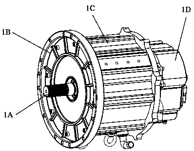
[0026] The difference from Embodiment 1 is that in the wheel drive assembly of electric heavy-duty vehicles in this embodiment, the permanent magnet synchronous motor 1 includes an output shaft 1A, a flange end cover 1B, a motor casing 1C, and a motor rear cover 1D , liquid inlet 1E, liquid outlet 1F, lifting ring 1G, power cable interface 1H, control signal cable interface 1J;

[0027] The motor casing 1C is the bearing and protection structure of the permanent magnet synchronous motor 1. The front end of the motor casing 1C is fixedly packaged with a flange end cover 1B, and the rear end of the motor casing 1C is fixedly packaged with a motor back cover 1D; the output shaft 1A is driven by a permanent magnet synchronous motor. The flange end cover 1B of the front end of the motor 1 passes through the body, and one end of the output shaft 1A is connected with the rotor of the motor, and the other end has a spline structure, which is used to connect with the wheel of the heavy-...

specific Embodiment approach 3

[0031] Different from the second specific embodiment, the wheel drive assembly of the electric heavy-duty vehicle in this embodiment, such as Figure 6-Figure 7 As shown, the motor driver 2 includes a driver outer shell 2A, a fixed frame 2B, and a connecting block 2C. A control system for controlling the permanent magnet synchronous motor 1 is installed inside the driver outer shell 2A, and a connecting block 2B is connected to the lower surface of the driver outer shell 2A. With the fixed frame 2C, the driver housing 2A is fixed with the motor casing 1C of the permanent magnet synchronous motor 1 through the connecting block 2B and the fixed frame 2C;

[0032] A row of copper column mounting holes 2D and a control signal cable passing hole 2E are provided on the mounting surface at the bottom of the connection block 2C. Since the permanent magnet synchronous motor 1 is a three-phase motor, the power cables are divided into A, B, and C. Similar as Figure 8 As shown, there a...


PUM


Abstract

An electric heavy-duty vehicle wheel rim driving assembly belongs to the field of electric motors. A conventional automotive motor system has a low degree of integration and a high cost. In the electric heavy-duty vehicle wheel rim driving assembly, a motor driver (2) is fixed to the upper end of a permanent magnet synchronous motor (1) and the motor driver and the permanent magnet synchronous motor constitute an assembly structure; a cooling pipe (3) comprises an S-shaped bent flat structure and a spirally coiled cylindrical structure in communication with each other; the S-shaped bent flat structure is installed in the motor driver (2) to dissipate the heat of the motor driver (2); a corresponding opening is disposed on the casing of the motor driver (2) for passing the S-shaped bent flat structure; and the spirally coiled cylindrical structure wraps the periphery of the permanent magnet synchronous motor (1) to dissipate the heat of the permanent magnet synchronous motor (1). The motor of the invention has a high degree of integration and low production and operation cost.

Description

technical field [0001] The invention relates to an electric heavy-duty vehicle wheel side drive assembly. Background technique [0002] Nowadays, automobile design is more and more concerned about the lightweight and integration of the whole vehicle under the premise of reliability and safety. The lightweight and integration of the whole vehicle is a trend in the development of automobiles. In hybrid (main drive motor) or pure electric vehicles, the driving mode of the vehicle will develop from a centralized driving mode to a distributed driving mode. The power and torque of the centralized drive system will be distributed to 2 or 4 drive wheel motor systems: for example, an A00-level pure electric vehicle is equipped with a 40kw drive motor system, and 2 wheel drive systems use 20kw for each wheel Drive motor system, if 4 wheel side motor systems are used, each wheel side motor system, such as figure 1 shown. [0003] The patent with the publication number CN 108312784A ...

Claims


Application Information

Patent Timeline
IPC IPC(8): H02K11/33H02K5/20H02K9/19B60K7/00B60K11/02
CPCB60K7/0007B60K11/02H02K5/20H02K9/19H02K11/33
Inventor 王震黄晨彬陆殷杰谢颖豪杨希洪彬
Owner 深圳数翔科技有限公司
Why Eureka
Try Eureka