Road roller transmission system and road roller

A transmission system and road roller technology, applied in the field of road rollers, can solve the problems of high failure rate, complex internal structure of drive axle of transmission system, high manufacturing cost, etc.

Pending Publication Date: 2021-01-22
SANY AUTOMOBILE MFG CO LTD
View PDF0 Cites 0 Cited by
  • Summary
  • Abstract
  • Description
  • Claims
  • Application Information

AI Technical Summary

Problems solved by technology

The current full-hydraulic road rollers are usually driven by hydraulic motors connected to the driving axle. The overall transmission system and the internal structure of the driving axle are relatively complicated. The driving axle is equipped with a planetary reducer and a parking brake. The structure of the bridge is specially designed, and the manufacturing cost is high

Method used


Image

  • Road roller transmission system and road roller
  • Road roller transmission system and road roller
  • Road roller transmission system and road roller

Examples


Embodiment 1

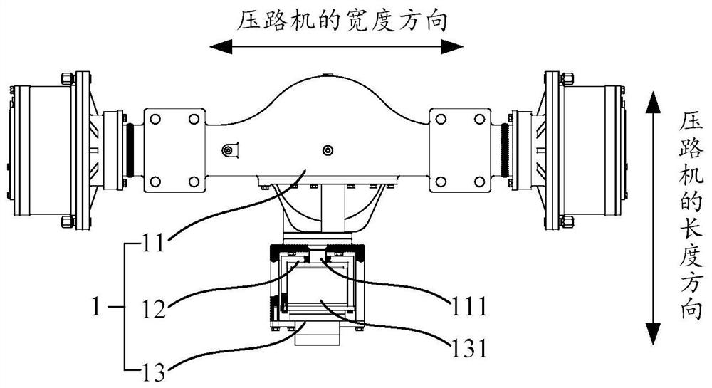
[0045] In this embodiment, a road roller transmission system 1 is provided, which is used for a road roller. like figure 1 As shown, the road roller transmission system 1 includes a driving axle 11 , a connecting mechanism 12 and an integrated speed reducer 13 .

[0046] The driving axle 11 is used to transmit power to the driving wheels of the road roller. The connecting mechanism 12 is located between the drive axle 11 and the integrated speed reducer 13, and the connecting mechanism 12 is connected with the input shaft 111 of the drive axle 11 and the output shaft 131 of the integrated reducer 13, so that the integrated reducer 13 and The drive axle 11 realizes the transmission connection. The input end 132 of the integrated reducer 13 is connected with the hydraulic driving device of the road roller to obtain the output power of the hydraulic driving device. Wherein, the integrated speed reducer 13 integrates the functions of deceleration and braking.

[0047] When the...

Embodiment 2

[0050] This embodiment provides a road roller transmission system 1, which is further improved on the basis of the first embodiment.

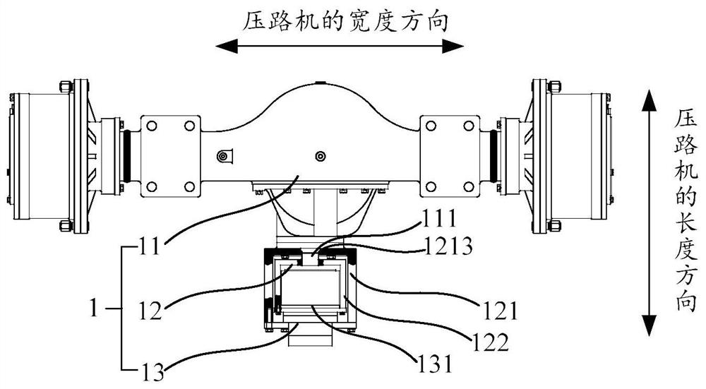
[0051] like figure 2 As shown, the connection mechanism 12 includes a mounting bracket 121 and a transmission flange 122 . The mounting bracket 121 is connected to the driving axle 11 and is located on a side of the driving axle 11 facing the integrated reducer 13 . The first through hole 1213 is arranged on the mounting bracket 121 corresponding to the input shaft 111 of the driving axle 11 , the input shaft 111 of the driving axle 11 passes through the first through hole 1213 and extends into the mounting bracket 121 , and is connected with the transmission flange 122 The end of the transmission flange 122 away from the drive axle 11 is connected to the output shaft 131 of the integrated reducer 13, so that the integrated reducer 13 and the drive axle 11 form a transmission connection, and between the integrated reducer 13 and the drive axl...

Embodiment 3

[0054] This embodiment provides a road roller transmission system 1, which is further improved on the basis of the second embodiment.

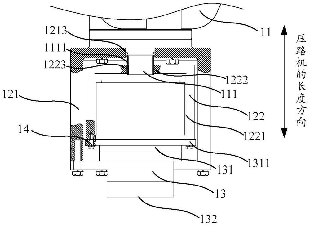
[0055] like figure 2 and image 3 As shown, the transmission flange 122 is provided with a groove 1221 toward the end of the integrated reducer 13, and the groove 1221 is recessed in a direction away from the integrated reducer 13; the output shaft 131 of the integrated reducer 13 extends into the groove 1221 and connected with the transmission flange 122. The shape of the groove 1221 is adapted to the shape of the output shaft 131 of the integrated reducer 13 for easy connection. Wherein, the output shaft 131 of the integrated reducer 13 is detachably connected to the transmission flange 122, which is convenient for disassembly and assembly.

[0056] Further, the output shaft 131 of the integrated reducer 13 is provided with a first stepped portion 1311 protruding in the radial direction. The first stepped portion 1311 is fixedly connect...


PUM


Abstract

The invention provides a road roller transmission system and a road roller. The road roller transmission system comprises: a drive axle; a connecting mechanism connected with an input shaft of the drive axle; and an integrated speed reducer, wherein the output shaft of the integrated speed reducer is connected with the connecting mechanism, and the input end of the integrated speed reducer is usedfor being connected with a driving device of the road roller. The integrated speed reducer is used for transmitting output power of the driving device to the driving axle and carrying out speed reduction and/or braking in the power transmission process. According to the technical scheme, the integrated speed reducer is adopted for transmission, speed reduction and/or braking operation, the overall structure and the connection relation of a transmission system are simplified, meanwhile, the internal structure of the drive axle is simplified, the drive axle high in universality in the mechanical industry can be adopted, the reliability of the drive axle can be improved, and meanwhile the cost can be reduced.

Description

technical field [0001] The present application relates to the technical field of a road roller transmission system, in particular, to a road roller transmission system and a road roller. Background technique [0002] The road roller is one of the commonly used road construction machinery. In recent years, the use of the full hydraulic drive system in the road roller has become more common, and the full hydraulic drive road roller has been developed rapidly. The current full-hydraulic road rollers mostly use hydraulic motors to connect drive axles for transmission. The overall transmission system and the internal structure of drive axles are relatively complex. The drive axles are equipped with planetary reducers and parking brakes, which have a high failure rate and need to be adjusted. The structure of the bridge is specially designed, and the manufacturing cost is high. SUMMARY OF THE INVENTION [0003] According to the embodiments of the present invention, it is intend...

Claims


Application Information

Patent Timeline
Patent Type & Authority Applications(China)
IPC IPC(8): E01C19/26B60K17/10
CPCB60K17/10E01C19/26
Inventor 贾干杜斌刘吉安
Owner SANY AUTOMOBILE MFG CO LTD
Why Eureka
Try Eureka