Carbon free car

A carbon-free trolley and frame technology, applied in the field of machinery, can solve problems that are not suitable for trolleys without carbon, low cost, inability to accurately adjust the front wheel angle, and inability to adapt to competition venues, etc., to improve energy conversion efficiency and improve The effect of accurate precision and simple structure

Inactive Publication Date: 2020-10-16
CENTRAL SOUTH UNIVERSITY OF FORESTRY AND TECHNOLOGY
View PDF10 Cites 0 Cited by
  • Summary
  • Abstract
  • Description
  • Claims
  • Application Information

AI Technical Summary

Problems solved by technology

First, the driving device of the trolley wraps the traction rope directly on the wheel drive shaft, resulting in a small starting torque of the trolley, which is not conducive to the start of the trolley, and at the same time affects the driving distance of the trolley
Second, when debugging the car, due to the influence of the winding position and the length of the traction rope, the angle of the front wheel cannot be adjusted accurately, which causes inconvenience in debugging and affects the obstacle-crossing driving of the car
Third, there is no pitch-changing device in the trolley mechanism, which cannot adapt to competition venues with obstacles of different distances
Fourth, the components of the trolley are too complicated, and the processing cost is high, which does not meet the requirements of carbon-free and low-cost trolleys.

Method used


Image

  • Carbon free car
  • Carbon free car
  • Carbon free car

Examples


Embodiment Construction

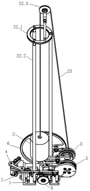
[0033] Combine below Figure 1 to Figure 6 The embodiments of the present invention will be described in detail.

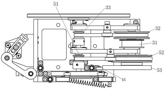
[0034] The carbon-free trolley includes a frame 1, which is characterized in that the frame 1 is equipped with a weight power assembly 2 that converts the gravitational potential energy of the weight into kinetic energy, an active pulley assembly 3, and a weight power assembly 2 connected to it. The crank connecting rod assembly 4, the driven cam assembly 5 connected to the driving pulley assembly 3 and used to push the crank connecting rod assembly 4 to move, the driving wheel 6 connected to the driving pulley assembly 3, and the crank connecting rod assembly 4 The steering wheels 7 and the driven wheels 8 rotatably mounted on the frame 1 are the driving wheels 6, the steering wheels 7 and the driven wheels 8 are distributed in a triangle shape, and respectively contact the ground to prop up the frame 1 horizontally, The steering wheel 7 is located in front of the ...


PUM


Abstract

The invention discloses a carbon-free trolley. The carbon-free trolley comprises a trolley frame and is characterized in that a weight power assembly capable of converting gravitational potential energy of a weight into power energy, a drive belt wheel assembly connected with the weight power assembly, a crank connecting rod assembly, a driven cam assembly connected with the drive belt wheel assembly and used for pushing the crank connecting rod assembly to move, a drive wheel connected with the drive belt wheel assembly, a steering wheel connected with the crank connecting rod assembly and adriven wheel rotatably installed on the trolley frame are installed on the trolley frame, the drive wheel, the steering wheel and the driven wheel are in a triangular distribution and respectively make contact with the ground to horizontally support the trolley frame, the steering wheel is located in front of the drive wheel and driven wheel, the weight power assembly pulls the drive belt wheel assembly to move through lowering of the weight, and therefore the driven cam assembly and the driven wheel are driven to move; the crank connecting rod assembly moves with the driven cam assembly, thesteering wheel is driven to steer, and the driven wheel rolls with moving of the driven wheel and the steering wheel to make the trolley run.

Description

Technical field [0001] The invention relates to a carbon-free trolley, belonging to the technical field of machinery. Background technique [0002] A race-type carbon-free car, which requires: design a self-propelled car with directional control function driven by gravitational potential energy. The energy required for the car to complete all actions during the walking process is converted from the given gravitational potential energy. Use energy from any other source. The trolley is required to have a steering control mechanism, and the steering control mechanism has an adjustable function to adapt to competition venues with obstacles at different intervals. The trolley is required to have a three-wheel structure. The given gravitational potential energy is obtained by a standard weight of 1Kg, and the lowering height of the weight is required to be 400±2mm. The width of the track is 2 meters, and the distance between the starting end line and the first obstacle and the dista...

Claims


Application Information

Patent Timeline
Patent Type & Authority Patents(China)
IPC IPC(8): A63H17/00A63H17/26A63H17/36
CPCA63H17/00A63H17/26A63H17/36
Inventor 庞国友高自成李立君赵凯杰王晓晨林泽帆
Owner CENTRAL SOUTH UNIVERSITY OF FORESTRY AND TECHNOLOGY
Why Eureka
Try Eureka