Charging protection circuit and method and switching power supply

A charging protection, switching power supply technology, applied in electrical components, adjusting electrical variables, instruments, etc., can solve the problems of reduced charging current and reduced charging efficiency, and achieve the effect of ensuring charging efficiency and maintaining stable charging current.

Inactive Publication Date: 2021-03-12
GREE ELECTRIC APPLIANCES INC
View PDF7 Cites 1 Cited by
  • Summary
  • Abstract
  • Description
  • Claims
  • Application Information

AI Technical Summary

Problems solved by technology

[0005] The embodiment of the present invention provides a charging protection circuit, method and switching power supply to solve the problem in

Method used


Image

  • Charging protection circuit and method and switching power supply
  • Charging protection circuit and method and switching power supply
  • Charging protection circuit and method and switching power supply

Examples


Embodiment 1

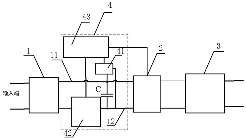
[0056] This embodiment provides a charging protection circuit, which is applied to a switching power supply. The structure of the switching power supply can be a topology with a DC-to-DC function such as BUCK, BOOST, flyback, forward, half-bridge, and full-bridge, or a corresponding topology circuit. out of shape. Since the wide range of input voltage usually uses the flyback topology or its derivative topology, this design takes the flyback topology as an example, figure 1 It is a diagram of the connection relationship between the charging protection circuit and the circuit of the switching power supply according to the embodiment of the present invention, such as figure 1As shown, the switching power supply includes: a rectifier 1, an inverter 2 and a transformer 3, wherein the rectifier and the inverter are connected through a first line 11 at the input end and a second line 12 at the input end;

[0057] The charging protection circuit 4 includes: a first sampling module 4...

Embodiment 2

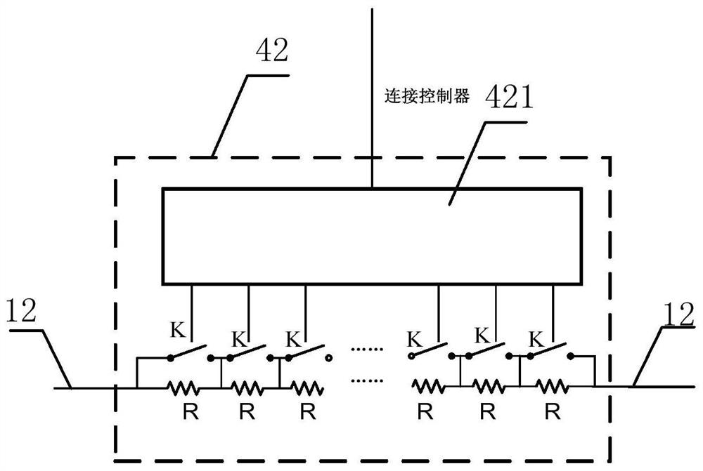
[0062] This embodiment provides another charging protection circuit, figure 2 is a structural diagram of an adjustable resistance module according to an embodiment of the present invention, in order to realize the adjustment of charging resistance, such as figure 2 As shown, the adjustable resistance module 42 includes: at least two charging resistors R and at least two first switches, the charging resistors R are connected in series, and the first switches K are connected in parallel to both ends of the charging resistors R one by one. When a certain first switch K is turned on, the charging resistor R connected in parallel with it will be short-circuited. Therefore, it will not be connected to the circuit. It can be seen that the more the number of first switches K that are turned on, the short-circuited The more charging resistors R are, since the adjustable resistor module 42 is a series circuit, its total resistance value is the sum of the resistance values ​​of the cha...

Embodiment 3

[0072] This embodiment provides a charging protection method, Figure 5 It is a flowchart of a charging protection method according to an embodiment of the present invention, such as Figure 5 As shown, the method includes:

[0073] S101. Obtain the bus capacitor voltage of the switching power supply.

[0074] According to the circuit structure in the above embodiment, the sum of the bus capacitor voltage and the voltage at both ends of the adjustable resistance module is equal to the input terminal voltage of the switching power supply, and the input terminal voltage is relatively stable. As the charging process continues, the bus capacitor voltage doubles. The voltage at both ends of the adjustable resistor module gradually increases, so the voltage at both ends of the adjustable resistor module decreases gradually, thereby reducing the charging current. , therefore, the bus capacitor voltage of the switching power supply needs to be obtained first.

[0075] S102, adjusti...


PUM


Abstract

The invention discloses a charging protection circuit and method and a switching power supply. The charging protection circuit comprises a first sampling module, used for detecting the voltage of a bus capacitor; wherein the bus capacitor is arranged between an input end first line and an input end second line of the switching power supply; an adjustable resistance module, arranged on the second line of the input end and used for keeping the charging current of the bus capacitor stable through the change of the resistance value of the adjustable resistance module; a controller, the input end of the controller being connected with the first sampling module, and the output end of the controller being connected with the adjustable resistor module for adjusting the resistance value of the adjustable resistor module according to the bus capacitor voltage. According to the invention, when the voltage of the bus capacitor rises, the charging resistance is correspondingly controlled to be reduced, so that the charging current is kept stable, and the charging efficiency is ensured.

Description

technical field [0001] The invention relates to the technical field of electronic power, in particular to a charging protection circuit, method and switching power supply. Background technique [0002] With the call and investment of the country's "energy saving and emission reduction, low-carbon life", switching power supply is an important part of the power supply family, and it has high-efficiency energy conversion, low energy loss, and saves a lot of copper, steel and occupied. Due to the characteristics of the land area, the switching power supply has developed rapidly in China in recent years. In order to further improve the efficiency of energy conversion and the stability of the switching power supply, a suitable charging protection circuit is conducive to the stability and high conversion efficiency of the switching power supply. [0003] Due to the existence of the bus capacitance of the switching power supply, it is often necessary to set a charging resistor at t...

Claims


Application Information

Patent Timeline
IPC IPC(8): H02M1/32H02M3/00
CPCH02M1/32H02M3/00
Inventor 谭亮李秋莲曾云洪
Owner GREE ELECTRIC APPLIANCES INC
Why Eureka
Try Eureka