
Eddy current flaw detection device

An eddy current flaw detection and detection device technology, applied in measuring devices, instruments, sorting and other directions, can solve problems such as heavy workload, fatigue, misoperation, etc., and achieve the effect of reducing workload and continuous operation.

Inactive Publication Date: 2021-03-16
浙江腾龙精线有限公司
View PDF9 Cites 1 Cited by
  • Summary
  • Abstract
  • Description
  • Claims
  • Application Information

AI Technical Summary

Problems solved by technology

[0003] Existing eddy current flaw detectors are usually used together with the feed track and the discharge track. The feed track, eddy current flaw detector, and discharge track are arranged in sequence. The worker places the steel bar on the feed track, and the steel bar is transported to the The flaw detection is carried out at the eddy current flaw detector. After the flaw detection is completed, the steel bar is transported to the discharge track, and then manually removed by the workers, and the workers need to classify according to the flaw detection results. Therefore, the workers need to continue to work, and the workload is heavy. It is prone to fatigue and misoperation, which is not conducive to stable and continuous operation

Method used


Image

  • Eddy current flaw detection device
  • Eddy current flaw detection device
  • Eddy current flaw detection device

Examples


Embodiment 1

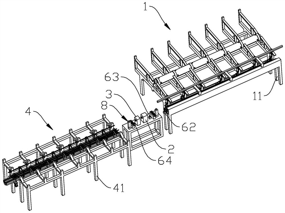
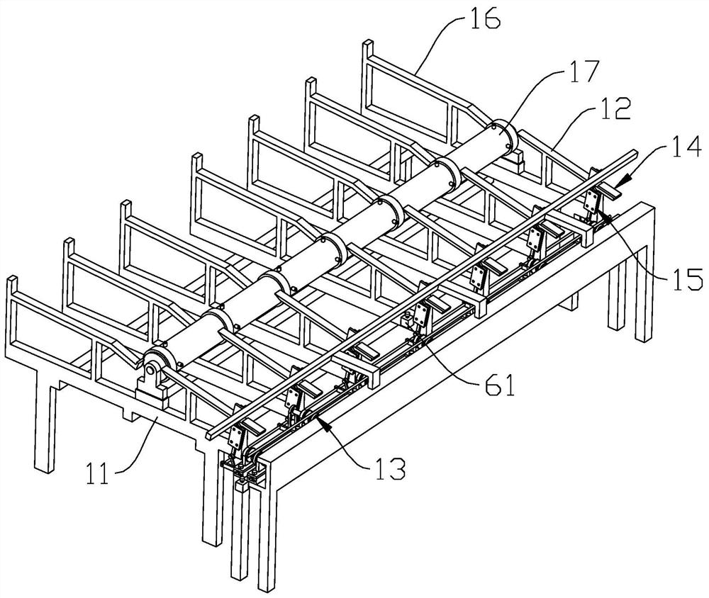
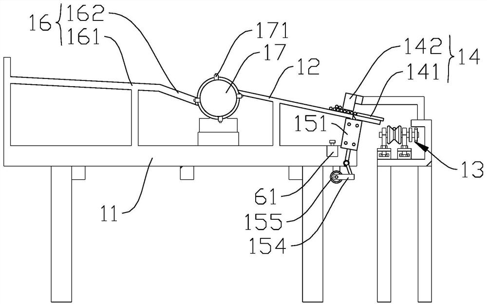
[0028] Embodiment 1: As shown in the figure, an eddy current flaw detection device includes a feeding mechanism 1, an eddy current flaw detector 2, a marking machine 3 and a feeding mechanism 4 arranged in sequence from front to back. The feeding mechanism 1 includes a first Underframe 11, the first underframe 11 is provided with a plurality of inclined first bottom plates 12 and feed rails 13 located obliquely below the plurality of first bottom plates 12, and the first bottom plate 12 is provided with a limit assembly 14 and a push assembly 15. The limit assembly 14 includes a first limit plate 141 fixedly arranged on the first bottom plate 12 and a second limit plate 142 located above the first bottom plate 12 , between the second limit plate 142 and the first bottom plate 12 A first passage for a steel rod is formed, and a second passage for a steel rod is formed between the second limiting plate 142 and the first limiting plate 141. The two passages are connected, and the...

Embodiment 2

[0031] Embodiment two: all the other parts are the same as embodiment one, and its difference is that the second bottom plate 16 of a plurality of inclinations, roller shaft 17 and the second driving motor ( not shown in the figure), the roller shaft 17 is located between the obliquely lower part of the second base plate 16 and the obliquely upper part of the first base plate 12, and the roller shaft 17 is provided with multiple sets of shifting block groups along the axial direction, and the shifting block groups consist of It consists of a plurality of shifting blocks 171 equidistantly distributed on the side wall of the roller shaft 17. When the roller shaft 17 rotates, the steel rod on the second bottom plate 16 can be lifted up by the shifting blocks 171 and turned towards the first bottom plate 12. , and finally fall on the first bottom plate 12.

[0032] In this embodiment, the second bottom plate 16 includes a first folded edge 161 and a second folded edge 162 that are...

Embodiment 3

[0035] Embodiment 3: the remaining parts are the same as Embodiment 1, the difference is that the first turning unit 43 includes a plurality of first support frames 431 fixedly arranged on the second chassis 41, a first rotating rod 432, and drives the first The first rotation driver 433 and a plurality of first hooks 434 for the rotation of the rotation rod 432, the first support frame 431 is provided with a first through hole, the first rotation rod 432 passes through all the first through holes and rotates with the first through hole, The tail end of the first hook 434 is fixedly connected with the first rotating rod 432, and the head of the first hook 434 extends to the position between the discharge track 44 and the steel bar; A plurality of second supporting frames 451 on the second chassis 41, a second rotating rod 452, a second rotating driver 453 and a plurality of second hooks 454 that drive the second rotating rod 452 to rotate, the second supporting frame 451 is pro...


PUM


Abstract

The invention discloses an eddy current flaw detection device which comprises a feeding mechanism, an eddy current flaw detector, a marking machine and a discharging mechanism which are sequentially arranged from front to back. The feeding mechanism comprises a first bottom frame; a plurality of inclined first bottom plates and a feeding rail located below the first bottom plates are arranged on the first bottom frame; limiting assemblies and ejecting pushing assemblies are arranged on the first bottom plates; the discharging mechanism comprises a second bottom frame, a good product containingframe, a first overturning unit, a discharging track, a second overturning unit and a defective product containing frame, wherein the good product containing frame, the first overturning unit, the discharging track, the second overturning unit and the defective product containing frame are sequentially arranged on the second bottom frame from left to right; and the discharging track, the eddy current flaw detector, the marking machine and the feeding track are located on the same straight line. The eddy current flaw detection device has the advantage of stability facilitating and continuous operation.

Description

technical field [0001] The invention belongs to the technical field of eddy current flaw detection, in particular to an eddy current flaw detection detection device. Background technique [0002] The eddy current flaw detector is a kind of flaw detection equipment that uses the principle of electromagnetic induction to detect the surface defects of metal components. Information, metal components such as steel rods. [0003] Existing eddy current flaw detectors are usually used together with the feed track and the discharge track. The feed track, eddy current flaw detector, and discharge track are arranged in sequence. The worker places the steel bar on the feed track, and the steel bar is transported to the The flaw detection is carried out at the eddy current flaw detector. After the flaw detection is completed, the steel bar is transported to the discharge track, and then manually removed by the workers, and the workers need to classify according to the flaw detection res...

Claims


Application Information

Patent Timeline
IPC IPC(8): B07C5/344B07C5/36B07C5/02G01N27/90
CPCB07C5/344B07C5/36B07C5/02G01N27/9093
Inventor 蒋超廖夕均叶清谢大凯袁方明
Owner 浙江腾龙精线有限公司
Learn More