Protection device of thread rolling machine

A technology of a protection device and a tooth rolling machine, which is applied in the field of tooth rolling machines, can solve problems such as function reduction, damage to the tooth rolling machine, and no protection function of the tooth rolling machine, so as to achieve the effect of improving functionality, safety, and practicability

Pending Publication Date: 2021-03-16
太仓琪威金属制品有限公司
View PDF12 Cites 0 Cited by
  • Summary
  • Abstract
  • Description
  • Claims
  • Application Information

AI Technical Summary

Problems solved by technology

[0003] In the existing technology, the tooth rolling machine for bolt processing has no protection function. When the tooth rolling machine is used in the factory, it has no protective measures. After a long time of use, a large amount of dust will accumulate on the surface and inside the machine body, which will cause tooth rolling for a long time. machine failure, and the impact of external force will cause damage to the thread rolling machine, affect its use, and cause its function to be reduced; and the existing thread rolling machine for bolt processing does not have the function of self-guiding material collection. After the bolt thread rolling process is completed, it can only Export the processed bolts out of the thread rolling body, but cannot automatically export them for collection, resulting in reduced practicability

Method used


Image

  • Protection device of thread rolling machine
  • Protection device of thread rolling machine
  • Protection device of thread rolling machine

Examples


Embodiment Construction

[0022] The following will clearly and completely describe the technical solutions in the embodiments of the present invention with reference to the accompanying drawings in the embodiments of the present invention. Obviously, the described embodiments are only some, not all, embodiments of the present invention. Based on the embodiments of the present invention, all other embodiments obtained by persons of ordinary skill in the art without making creative efforts belong to the protection scope of the present invention.

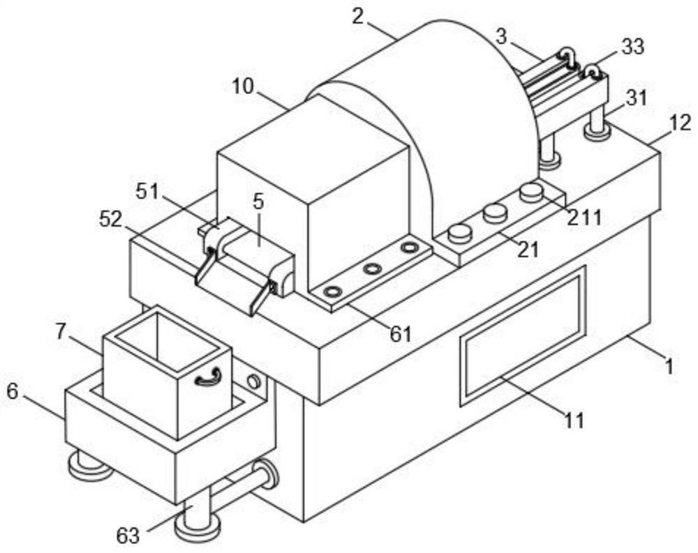
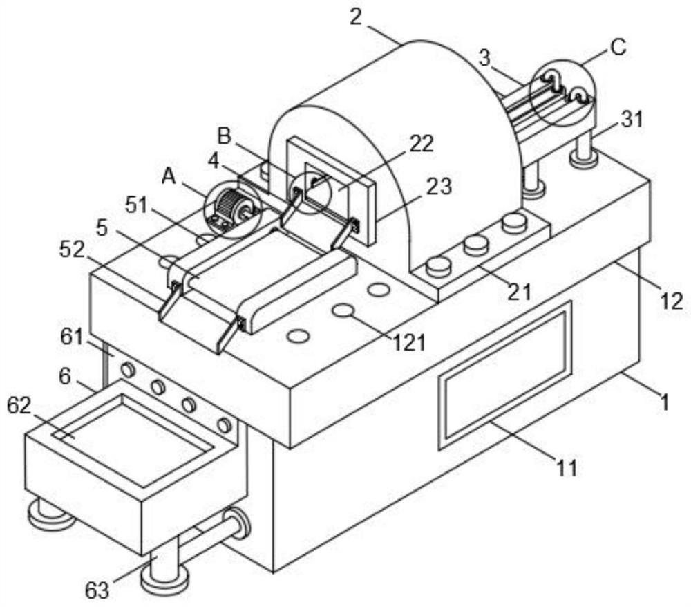
[0023] see Figure 1~5 , in an embodiment of the present invention, a protection device for a tooth rolling machine includes a base 1 and a protective cover 10, a side door 11 is installed on the right side wall of the base 1, a processing table 12 is arranged on the upper end of the base 1, and the front part of the upper end of the processing table 12 is The left and right sides are all provided with a plurality of installation holes 121, and the tooth rubbi...


PUM


Abstract

The invention discloses a protection device of a thread rolling machine in the field of thread rolling machines. The protection device comprises a base and a protection cover, wherein a side door is installed on the right side wall of the base; a machining table is arranged at the upper end of the base; a plurality of mounting holes are formed in the left side and the right side of the front partof the upper end of the machining table; the thread rolling machine is installed at the rear part of the upper end of the machining table; first fixing seats are fixedly connected to the left side andthe right side of the lower end of the thread rolling machine; a plurality of fixing bolts are installed on the first fixing seats on the two sides; an outlet is formed in the front end wall of the thread rolling machine; a limiting plate is installed outside the outlet; a conveying belt is installed inside the outlet; side plates are installed on the left side and the right side of the upper endof the conveying belt; the protection cover is installed at the upper end of the front part of the machining table through the cooperation of the plurality of bolts and the mounting holes; and the upper parts of a material conveying mechanism and a driving machine are covered through the protection cover. During use, the protection cover is beneficial to protecting the material conveying mechanism and the driving machine, dust and impurities are prevented from falling into the surfaces of the material conveying mechanism and the driving machine, damage caused by collision of external force isavoided, and the functionality and the safety of the protection device are improved.

Description

technical field [0001] The invention relates to the field of tooth rolling machines, in particular to a protection device for tooth rolling machines. Background technique [0002] The thread rolling machine is a kind of processing equipment for the outer surface of the cylindrical workpiece. It is two pieces of the same thread rolling surface with the same helix angle as the tooth shape of the bolt thread. When the thread rolling boards move together, the two The bolt blank between the thread rolling boards rubs out the threads, and the thread rolling boards go back and forth one bolt thread at a time to complete the processing. The speed is quite high. The thread rolling is mostly used for small bolt processing. Summary: thread rolling is for the outer surface of cylindrical workpieces. processing. [0003] In the existing technology, the tooth rolling machine for bolt processing has no protection function. When the tooth rolling machine is used in the factory, it has no p...

Claims


Application Information

Patent Timeline
IPC IPC(8): B21H3/06F16P1/02
CPCB21H3/06F16P1/02
Inventor 杨井虎
Owner 太仓琪威金属制品有限公司
Why Eureka
Try Eureka