Cooling base assembling equipment for CPU cooler

A technology of heat dissipation base and assembly equipment, applied in metal processing equipment, drilling/drilling equipment, feeding device, etc., can solve the problems of unqualified products, prone to errors, slow assembly speed, etc., to achieve precise processing and prevent displacement , The effect of saving drilling time

Active Publication Date: 2021-03-16
湖南鑫辉科技发展有限公司
View PDF7 Cites 2 Cited by
  • Summary
  • Abstract
  • Description
  • Claims
  • Application Information

AI Technical Summary

Problems solved by technology

[0004] In order to overcome the shortcomings of slow assembly speed, low efficiency, and easy mistakes in the assembly process, resulting in unqualified products, the technical problem of the present invention is: to provide a fast assembly speed, high efficiency, high assembly technology, and low error rate. Lower CPU coolers are assembled with cooling bases

Method used


Image

  • Cooling base assembling equipment for CPU cooler
  • Cooling base assembling equipment for CPU cooler
  • Cooling base assembling equipment for CPU cooler

Examples


Embodiment 1

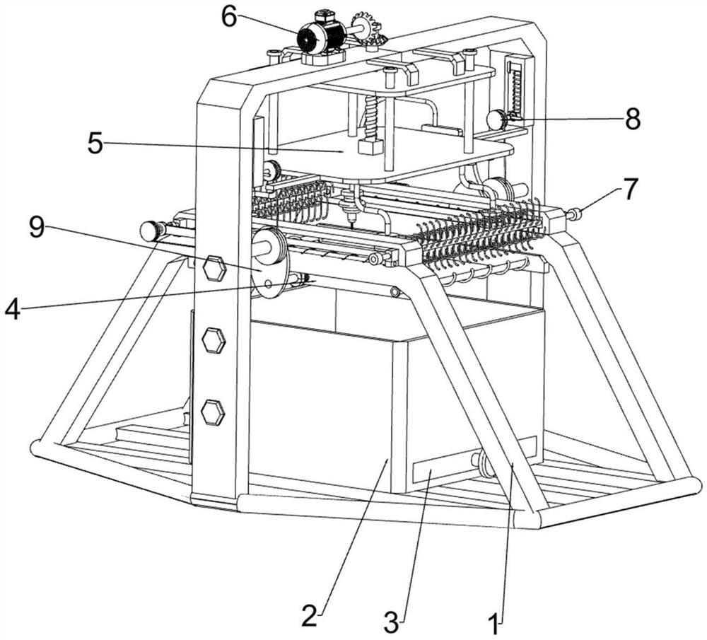
[0056] A CPU cooling base assembly equipment, such as figure 1 As shown, it includes a first fixed plate 1, a collection box 2, a drawer 3, a fixing mechanism 4 and a pressing mechanism 5, the first fixed plate 1 is provided with a collection box 2, and the lower part of the collection box 2 is slidingly connected with a drawer 3, A fixing mechanism 4 is arranged on the first fixing plate 1 , and a pressing mechanism 5 is arranged on the top of the first fixing plate 1 .

[0057] When people need to process the material, the material is placed on the fixing mechanism 4, and then the pressing mechanism 5 is manually operated to process the material, and the waste generated during the processing falls into the collection box 2. After the processing is completed, the manual stop By operating the pressing mechanism 5, people can take out the material from the fixing mechanism 4, and then pull the drawer 3 to remove waste materials. After the removal is completed, manually push the...

Embodiment 2

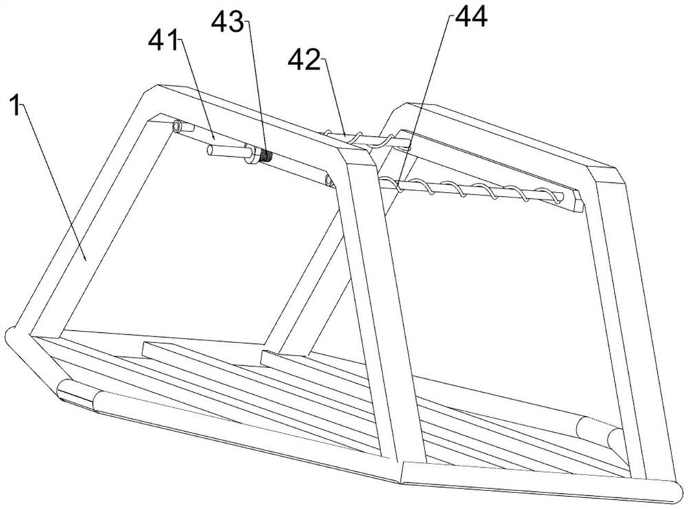
[0059] On the basis of Example 1, such as figure 2 As shown, the fixing mechanism 4 includes a splint 41, a first rod 42, a first spring 43 and a second spring 44. The front and rear sides of the middle part of the first fixing plate 1 are slidably connected to the splint 41, and the left and right sides of the splint 41 The first rod 42 is slidingly connected between them, the second spring 44 is connected between the left and right sides of the splint 41, and the second spring 44 is set on the first rod 42. A first spring 43 is provided between them.

[0060] Before people need to process the material, manually move the splint 41 to the outside. At this time, the material can be placed between the splints 41. At this time, the second spring 44 stretches and the first spring 43 compresses to adjust the material. After the position, people let go, the second spring 44 shrinks and resets, and the first spring 43 stretches and resets, driving the splint 41 to move to the insid...

Embodiment 3

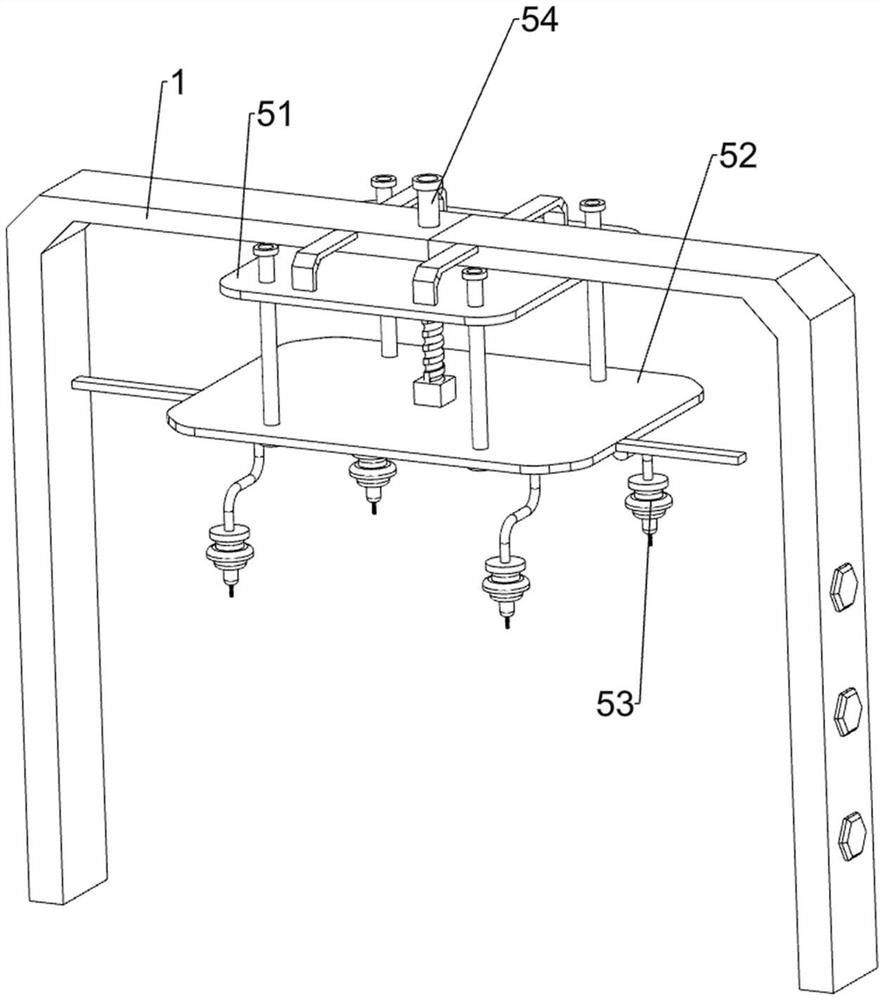
[0062]On the basis of Example 2, such as Figure 3 to Figure 8 As shown, the pressing mechanism 5 includes a second fixing plate 51, a lower pressing plate 52, an electric drill 53 and a screw 54, the top of the first fixing plate 1 is rotatably connected with a screw 54, and the bottom of the screw 54 is threadedly connected with a lower pressing plate 52. A second fixing plate 51 is arranged on the upper part of the fixing plate 1, and the second fixing plate 51 is slidably connected with the lower pressing plate 52, and four electric drills 53 are evenly distributed on the bottom of the lower pressing plate 52.

[0063] After the material is fixed, turn the screw 54 manually to start the electric drill 53. The screw 54 drives the lower platen 52 and the electric drill 53 to move downward. When the electric drill 53 is in contact with the material, the material is processed and drilled. 54, the screw rod 54 drives the lower platen 52 and the electric drill 53 to move upwards...


PUM


Abstract

The invention relates to assembling equipment, in particular to cooling base assembling equipment for a CPU cooler. The technical problem to be solved by the present invention is to provide the cooling base assembling equipment for the CPU cooler, and the cooling base assembling equipment is high in assembling speed, high in efficiency, high in assembling technology and low in error rate. The cooling base assembling device for the CPU cooler comprises: a collecting box, arranged on a first fixing plate; a drawer, slidably connected to one side of the collecting box; a fixing mechanism, arranged on the first fixing plate; and a pressing mechanism, arranged at the upper part of the first fixing plate. Under the action of a discharging mechanism, automatic discharging can be achieved, and themanual discharging time is saved; and through cooperation of a manual cleaning mechanism and an automatic cleaning mechanism, waste of the materials can be cleaned up.

Description

technical field [0001] The invention relates to an assembly device, in particular to a heat dissipation base assembly device for a CPU radiator. Background technique [0002] The Chinese name of the CPU is the central processing unit. It is one of the main equipment of the electronic computer. The core component that decodes and executes instructions, performs arithmetic and logic operations on data, or performs other information processing. When the CPU temperature is too high, if the temperature is not cooled, the computer will be in a dead state. While using the computer, it is necessary to cool down the CPU, and the CPU cooling base can solve the problem of excessive temperature of the PCU. [0003] In order to maximize the capacity of the radiator base, it is also necessary to ensure the smoothness and flatness of the radiator base, which depends on the technology of the radiator base in the assembly process, but the current assembly is largely dependent on manual asse...

Claims


Application Information

Patent Timeline
Patent Type & Authority Applications(China)
IPC IPC(8): B23B41/00B23B39/16B23Q3/00B23Q5/34B23Q7/00B23Q11/00
CPCB23B41/00B23B39/161B23Q3/00B23Q5/34B23Q7/00B23Q11/0042B23Q11/0067Y02D10/00
Inventor 曾宪军
Owner 湖南鑫辉科技发展有限公司
Why Eureka
Try Eureka