
Assembling device for filing shaft and toy gear

A technology for assembling devices and toys, which is applied in the direction of manufacturing tools, metal processing, metal processing equipment, etc., can solve the problems of low assembly efficiency and achieve high-precision assembly, high-precision and high-efficiency operations

Inactive Publication Date: 2021-03-16
王睿
View PDF0 Cites 0 Cited by
  • Summary
  • Abstract
  • Description
  • Claims
  • Application Information

AI Technical Summary

Problems solved by technology

[0003] The object of the present invention is to provide a filing shaft and toy gear assembly device, which has the advantages of quick assembly of the filing shaft and toy gear, and solves the problem of low assembly efficiency in the past

Method used

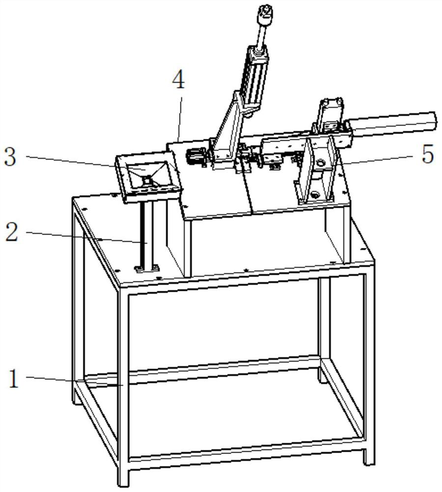

Image

  • Assembling device for filing shaft and toy gear
  • Assembling device for filing shaft and toy gear
  • Assembling device for filing shaft and toy gear

Examples


Embodiment 1

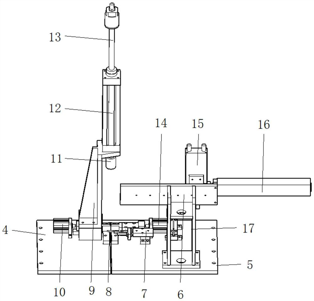
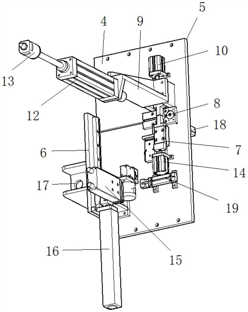
[0018] see Figure 1 to Figure 3 , the present invention provides a technical solution for an assembly device of a file shaft and a toy gear: a device for assembling a file shaft and a toy gear includes a machine 1 and an assembly mechanism 5, the assembly mechanism 5 is installed on the upper end surface of the machine 1, and the machine The upper end face bolt of platform 1 is fixed with support frame 2, and the top of support frame 2 is equipped with display screen 3, and display screen 3 is electrically connected with first motor 14, second motor 10, first cylinder 16 and second cylinder 12 respectively. Programming commands can be input through the display screen 3 , and the action control of the first motor 14 , the second motor 10 , the first cylinder 16 and the second cylinder 12 can be realized through the PLC controller built in the display screen 3 .

[0019] The assembly mechanism 5 includes a workbench 4, a second support 9 and a first support 17 are respectively ...

Embodiment 2

[0021] On the basis of Embodiment 1, the present invention further provides an embodiment of an assembly device for a file shaft and a toy gear: an assembly device for a file shaft and a toy gear, including a machine 1 and an assembly mechanism 5, and the assembly mechanism 5 is installed on The upper end surface of the machine platform 1, the upper end surface bolt of the machine platform 1 is fixed with a support frame 2, and the top of the support frame 2 is equipped with a display screen 3, and the display screen 3 is connected to the first motor 14, the second motor 10, and the first cylinder 16 respectively. It is electrically connected with the second cylinder 12. Programming commands can be input through the display screen 3 , and the action control of the first motor 14 , the second motor 10 , the first cylinder 16 and the second cylinder 12 can be realized through the PLC controller built in the display screen 3 .

[0022] The assembly mechanism 5 includes a workbenc...


PUM


Abstract

The invention discloses an assembling device for a filing shaft and a toy gear. The assembling device comprises a machine table and an assembling mechanism. The assembling mechanism is installed on the upper end face of the machine table, the assembling mechanism comprises a workbench, a second support and a first support are welded to the workbench, a second air cylinder is fixed to the second support through bolts, a stroke rod is installed on the second air cylinder, a stamping part is assembled at the front end of the stroke rod, a stroke protection plate is welded to the first support, afirst air cylinder is fixed to the outer end of the stroke protection plate through bolts, and a stamping mechanism is installed on a stroke rod of the first air cylinder. A second motor is fixed to the outer side, close to the second support, of the upper surface of the workbench through bolts, a first motor is fixed to the inner side, close to the first support, of the upper surface of the workbench through bolts, and a limiting plate and a base plate are installed on the upper surface of the workbench and located between the second support and the first support. According to the device, thepurpose of quickly assembling the filing shaft and the toy gear can be achieved.

Description

technical field [0001] The invention relates to the field of assembly technology, in particular to an assembly device for a filing shaft and a toy gear. Background technique [0002] Assembly refers to the process of assembling parts according to the specified technical requirements, and making them into qualified products after debugging and inspection. Assembly begins with the design of assembly drawings, which stipulates the assembly sequence of products and components, assembly methods, assembly technical requirements and Technical documents such as inspection methods and equipment required for assembly, fixtures, time, quotas, etc. There are four kinds of assembly methods: interchangeable assembly method, group assembly method, repair method, and adjustment method. The assembly process specification is a process document that stipulates the product or component assembly process specification and operation method. It is to formulate assembly plans and technical preparati...

Claims


Application Information

Patent Timeline
Patent Type & Authority Applications(China)
IPC IPC(8): B23P19/027
CPCB23P19/027
Inventor 王睿
Owner 王睿
Learn More