Bridge deck accessory component manufacturing mold and bridge deck accessory component manufacturing method

A technology of auxiliary components and manufacturing methods, which is applied in the direction of mold auxiliary parts, molds, manufacturing tools, etc., can solve problems such as unstable construction quality, affecting construction efficiency, and long construction period, so as to improve the quality of engineering entities and shorten the on-site construction period , Create simple and fast effects

Inactive Publication Date: 2021-03-16
THE SECOND CONSTR OF CTCE GROUP +1
View PDF7 Cites 5 Cited by
  • Summary
  • Abstract
  • Description
  • Claims
  • Application Information

AI Technical Summary

Problems solved by technology

[0002] At present, railway bridges account for a relatively large proportion of the total length of the line, and the auxiliary structures of the bridge deck mainly include protective walls, vertical walls, side walls, etc. The existing auxiliary structures of the box girder bridge deck need to be installed in blocks, which cannot be completed at one time, resulting in a long construction period. , many processes, large amount of cast-in-place operations, unstable construction quality, difficult maintenance operations, etc.
Each process needs to bind steel bars in advance, install formwork and pour concrete. Each process needs to be carried out in sequence and requires different formwork. In addition, it is difficult to transport the formwork on the construction site, which greatly affects the construction efficiency.

Method used


Image

  • Bridge deck accessory component manufacturing mold and bridge deck accessory component manufacturing method

Examples


Embodiment Construction

[0026] The following will clearly and completely describe the technical solutions in the embodiments of the present invention with reference to the accompanying drawings in the embodiments of the present invention. Obviously, the described embodiments are only some, not all, embodiments of the present invention. Based on the embodiments of the present invention, all other embodiments obtained by persons of ordinary skill in the art without making creative efforts belong to the protection scope of the present invention.

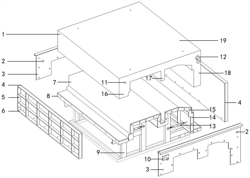
[0027] see figure 1 , in the embodiment of the present invention, a bridge deck auxiliary component manufacturing mold, including a bottom mold 7 and an end mold 3 detachably connected with the bottom mold 7, a side mold 4, the end mold 3 is provided with a core-pulling hole 2, and the core-pulling A core-pulling steel pipe 10 is movably inserted into the hole 2. Two end molds 3 are provided and are respectively connected to both ends of the bottom mold 7. The...


PUM


Abstract

The invention discloses a bridge deck accessory component manufacturing mold. The bridge deck accessory component manufacturing mold comprises a bottom mold body, two end mold bodies and two side moldbodies, the end mold bodies and the side mold bodies are detachably connected with the bottom mold body, the two end mold bodies are connected to the two ends of the bottom mold body correspondingly,the two side mold bodies are connected to the two sides of the bottom mold body correspondingly, and the bottom mold body, the end mold bodies and the side mold bodies define a box-shaped structure with the upper end open. The bottom mold body is provided with a groove used for containing a bridge deck accessory component, the groove is formed by connecting continuously-bent bottom plates, the adjacent bottom plates are rotationally connected, a back arris gap is formed between the adjacent bottom plates, and an adjusting rod for adjusting the relative positions of the bottom plates is arranged below the bottom mold body. The bridge deck accessory component manufacturing mold effectively overcomes the defects that many installation procedures are needed for a traditional bridge deck system protection wall, a vertical wall, a side wall and other bridge deck accessory structures, the number of adopted formworks is large, concrete pouring is carried out multiple times, the formwork dismounting and mounting process is tedious, formwork dismounting needs to wait for the concrete strength, all the procedures are carried out in sequence, the construction period is long, the number of users is large, and time and labor are wasted when materials are transported, disassembled and assembled.

Description

technical field [0001] The invention relates to the technical field of bridge engineering, in particular to a mold for making an accessory component of a bridge deck and a method for making an accessory component of a bridge deck. Background technique [0002] At present, railway bridges account for a relatively large proportion of the total length of the line, and the auxiliary structures of the bridge deck mainly include protective walls, vertical walls, side walls, etc. The existing auxiliary structures of the box girder bridge deck need to be installed in blocks, which cannot be completed at one time, resulting in a long construction period. , There are many processes, a large amount of cast-in-place operations, unstable construction quality, and difficult maintenance operations. Each process needs to bind steel bars in advance, install formwork and pour concrete. Each process needs to be carried out in sequence and requires different formwork. In addition, it is difficu...

Claims


Application Information

Patent Timeline
Patent Type & Authority Applications(China)
IPC IPC(8): B28B7/02B28B7/18B28B7/00B28B11/24B28B23/02B28B1/14
CPCB28B1/14B28B7/0002B28B7/0014B28B7/02B28B7/18B28B11/245B28B23/02
Inventor 任世朋冯成龙朱元元宋东旺曹思佳宋宝林
Owner THE SECOND CONSTR OF CTCE GROUP
Why Eureka
Try Eureka