Plastic particle packaging device for resource regeneration
A plastic granule and resource regeneration technology, applied in packaging, transportation and packaging, packaging item types, etc., can solve the problems of many operations, inability to adjust the discharge flow, and high labor costs
- Summary
- Abstract
- Description
- Claims
- Application Information
AI Technical Summary
Problems solved by technology
Method used
Image
Examples
Embodiment 1
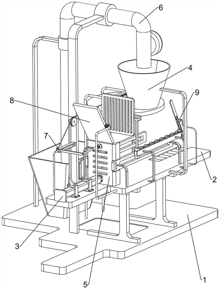
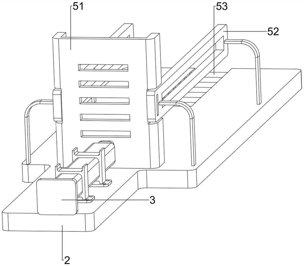
[0058] A plastic granule packaging device for resource regeneration, such as figure 1 As shown, it includes a bottom plate 1, a workbench 2, a cylinder 3, a discharge mechanism 4, and a push mechanism 5. A workbench 2 is arranged on the right side of the bottom plate 1, and a cylinder 3 is installed on the front side of the workbench 2. The middle part of the workbench 2 The left and right sides are provided with a discharge mechanism 4, and the front side of the top of the workbench 2 is provided with a push mechanism 5.
[0059] When people want to pack plastic granules, they can use this plastic granule packaging device for resource regeneration. First, the user places the carton on the workbench 2, starts the cylinder 3, and the cylinder 3 drives the pushing mechanism 5 to push the carton Into the material-discharging mechanism 4, the material-discharging mechanism 4 injects plastic particles into the carton to realize the packaging effect, and closes the cylinder 3 after ...
Embodiment 2
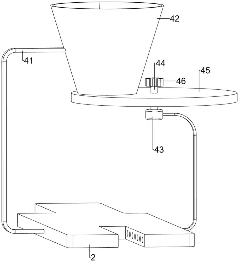
[0061] On the basis of Example 1, such as figure 2 and image 3 As shown, the discharge mechanism 4 includes a connecting rod 41, a hopper 42, a first rotating sleeve 43, a rotating shaft 44, a material closing plate 45 and a spur gear 46, the middle part of the right wall of the workbench 2 is provided with a connecting rod 41, and the connecting rod 41 left end A hopper 42 is provided, the middle part of the left wall of the workbench 2 is provided with a first rotating sleeve 43, the upper part of the first rotating sleeve 43 is provided with a rotating shaft 44, and the upper part of the rotating shaft 44 is provided with a material closing plate 45, which is in contact with the bottom of the hopper 42 , The top of the rotating shaft 44 is provided with a spur gear 46 .
[0062] The user pours plastic particles into the hopper 42, and then turns the spur gear 46, thereby driving the rotating shaft 44 to rotate, and then driving the material closing plate 45 to rotate, op...
Embodiment 3
[0066] On the basis of Example 2, such as Figure 4-Figure 7 As shown, it also includes a material suction mechanism 6. The left side of the bottom plate 1 is provided with a material suction mechanism 6. The material suction mechanism 6 includes a fixed sleeve 61, a material suction pipe 62, an air suction machine 63 and a raw material box 64. On the bottom plate 1 The front side is provided with a fixed sleeve 61, the upper part of the fixed sleeve 61 is provided with a suction pipe 62, the rear side of the suction pipe 62 is provided with a suction machine 63 on the right side, and the bottom plate 1 is provided with a raw material box 64 on the left side, and the raw material box 64 is located on the suction pipe. 62 below.
[0067] The user pours plastic particles into the raw material box 64, starts the air suction machine 63, and the air suction machine 63 sucks the plastic particles upwards, and the plastic particles enter the hopper 42 through the suction pipe 62 to r...
PUM
 Abstract
Description
Claims
Application Information
 - R&D
- Intellectual Property
- Life Sciences
- Materials
- Tech Scout
- Unparalleled Data Quality
- Higher Quality Content
- 60% Fewer Hallucinations
Browse by: Latest US Patents, China's latest patents, Technical Efficacy Thesaurus, Application Domain, Technology Topic, Popular Technical Reports.
© 2025 PatSnap. All rights reserved.Legal|Privacy policy|Modern Slavery Act Transparency Statement|Sitemap|About US| Contact US: help@patsnap.com


