Electronic component surface oxide removing device

A technology for surface oxides and electronic components, applied in the field of surface oxide removal devices for electronic components, can solve problems such as affecting product quality and damage to electronic components, and achieve the effect of saving manpower

Pending Publication Date: 2022-02-01
于都县八佰贸易有限公司
View PDF0 Cites 0 Cited by
  • Summary
  • Abstract
  • Description
  • Claims
  • Application Information

AI Technical Summary

Problems solved by technology

[0004] The object of the present invention is to provide an oxide removal device on the surface of electronic components that is easy to use, less damaged to electronic components and can reduce labor intensity, and can solve the problem that people use simple tools to clean the surface of electronic components in the above-mentioned background technology. The oxide on the surface is scraped off, but due to human factors, it is easy to cause damage to electronic components and affect product quality.

Method used


Image

  • Electronic component surface oxide removing device
  • Electronic component surface oxide removing device
  • Electronic component surface oxide removing device

Examples


Embodiment 1

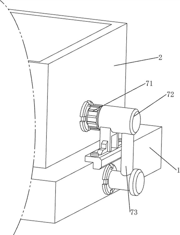
[0071] Such as Figure 1-2 As shown, a device for removing oxides on the surface of electronic components includes a first water tank 1, a second water tank 2, a derusting mechanism 4 and a feeding mechanism 5, the first water tank 1 is provided with a second water tank 2, and the second water tank 2 The upper side of the water tank 2 is provided with a derusting mechanism 4, and the derusting mechanism 4 is provided with a feeding mechanism 5.

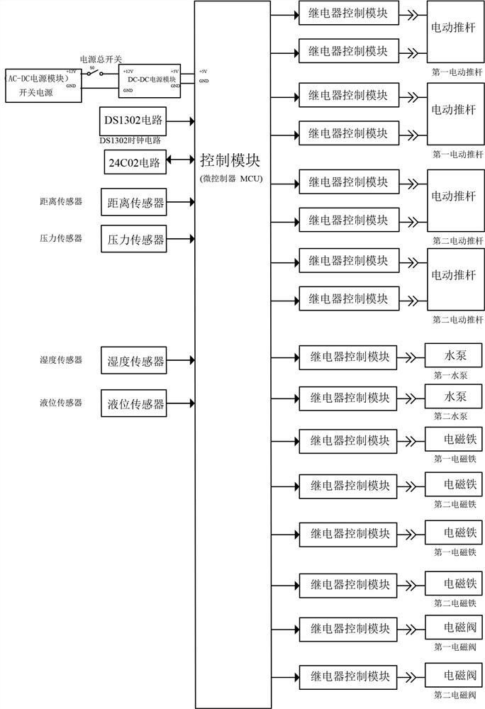
[0072] When people need to remove the surface oxide of electronic components, people need to press the main power switch to power on the device, and people need to pour the rust remover into the second water tank 2 first, and then put the electronic components in On the feeding mechanism 5, when the weight on the feeding mechanism 5 detected by the 5 parts of the feeding mechanism reaches the preset value in the control module, the 5 parts of the feeding mechanism send a signal, and the control module controls the operation of the fee...

Embodiment 2

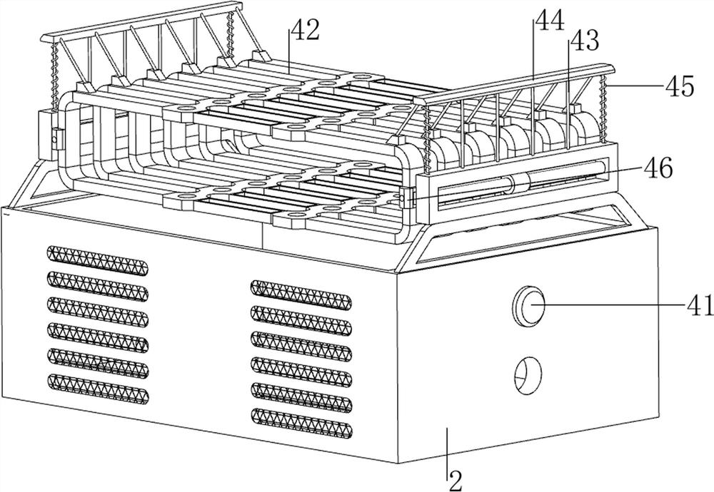
[0074] Such as Figure 3-17 As shown, the derusting mechanism 4 includes a liquid level sensor 41, a feeding part 42, a stay cord 43, a first electromagnet 44, a first spring 45, a magnetic block 46 and a sliding sleeve 47, and the outer wall of the second water tank 2 upper right side is arranged There is a liquid level sensor 41, and the left and right sides of the top of the second water tank 2 are slidingly provided with sliding sleeves 47, and the two sliding sleeves 47 are provided with magnetic blocks 46, and a feeding part 42 is arranged between the two magnetic blocks 46. Six stay cords 43 are connected between the left and right sides of the top of the discharge member 42 and the top of the second water tank 2, and the first electromagnet 44 is arranged between the six stay cords 43 on the same side in the longitudinal direction. The second water tank 2 cooperates, and the first spring 45 is all wound on the two stay cords 43 of the frontmost side and the two stay co...


PUM


Abstract

The invention relates to a removing device, in particular to an electronic component surface oxide removing device. The electronic component surface oxide removing device is convenient to use, small in damage to the electronic component and capable of reducing the labor intensity of workers. The electronic component surface oxide removing device comprises a first water tank and a second water tank, and the second water tank is arranged on the first water tank; and a rust removal mechanism is arranged on the upper side of the second water tank. According to the invention, the electronic components can be soaked in a rust remover through downward movement of a discharging component, oxides on the surfaces of the electronic components can be removed, and the rust removal effect is achieved; a telescopic rod of a first electric push rod is shortened to slide on a sliding block, so that a discharging plate is driven to move backwards, then electronic components, a pressure sensor and a fixing rod are driven to move backwards, the electronic components can be located in a discharging component by moving the discharging plate backwards, and the feeding effect is achieved.

Description

technical field [0001] The invention relates to a removal device, in particular to a device for removing oxides on the surface of electronic components. Background technique [0002] Electronic components are components of electronic components and small machines and instruments. They are often composed of several parts and can be used in similar products. They often refer to certain parts in industries such as electrical appliances, radios, and instruments. They are capacitors, transistors, The general term for electronic devices such as hairsprings and springs. In the production and processing of electronic products, electronic components are easily polluted due to various factors, causing oxides to be generated on the surface of electronic components. The residue of oxides on electronic components will affect the Therefore, it is necessary to process the electronic components with oxides on the surface. Generally, manual removal is used in processing plants. People use si...

Claims


Application Information

Patent Timeline
Patent Type & Authority Applications(China)
IPC IPC(8): C23G3/00C23G1/36
CPCC23G3/00C23G1/36
Inventor 万秀之
Owner 于都县八佰贸易有限公司
Why Eureka
Try Eureka