Adjustable locking pulley device and sliding rail door

An adjustable and pulley technology, which is applied to the suspension device of the wing leaf, the arrangement of windows/doors, and the wing leaf, etc., can solve the problems of affecting the structural stability, unable to install the door body and guide rail, narrow use range, etc. uniform force effect

Inactive Publication Date: 2021-03-16
尤梦宇
View PDF1 Cites 1 Cited by
  • Summary
  • Abstract
  • Description
  • Claims
  • Application Information

AI Technical Summary

Problems solved by technology

However, it still has the following deficiencies: first, it only has one pulley, and then only one pulley is used to support the single corner above the door body, which easily leads to the concentration of force on one pulley, which affects the stability of the structure and does not support the door body. The effect is not ideal, and the pulley is easy to damage; second, after locking, it can only rely on the fixed block to limit the pulley. When the distance between the edge of the door body and the guide rail is far, the pulley cannot contact the guide rail. When the distance between the edge of the door body and the guide rail is relatively close, it cannot be installed between the door body and the guide rail, and thus cannot meet the needs of different distances between the edge of the door body and the guide rail, and the use range is narrow

Method used


Image

  • Adjustable locking pulley device and sliding rail door
  • Adjustable locking pulley device and sliding rail door
  • Adjustable locking pulley device and sliding rail door

Examples


Embodiment Construction

[0024] The adjustable locking pulley device and the slide rail door of the present invention will be clearly and completely described below in conjunction with the accompanying drawings.

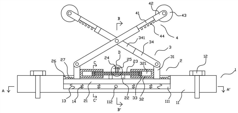
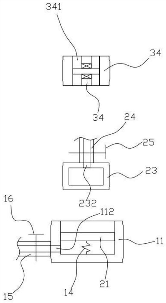
[0025] Such as Figure 1 to Figure 5 As shown, the adjustable locking pulley device 100 of the present invention includes a fixed plate structure 1, a first adjustment structure 2 arranged on the fixed plate structure 1, and a second adjustment structure 3 arranged on the first adjustment structure 2 . The pulley structure 4 arranged on the second adjustment structure 3 .

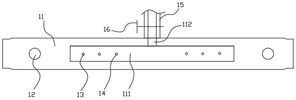
[0026] Such as Figure 1 to Figure 4 As shown, the fixed plate structure 1 includes a fixed plate 11, fasteners 12 arranged at both ends of the fixed plate 11, a number of limiting ropes 13 arranged on the fixed plate 11, a first spring 14, The first pipeline 15 outside the fixed plate 11 and the first valve 16 arranged on the first pipeline 15 . The fixed plate 11 is elongated. In this embodiment, the fixed plate 11 i...


PUM


Abstract

An adjustable locking pulley device comprises a fixing plate structure, a first adjusting structure, a second adjusting structure and a pulley structure, the fixing plate structure comprises a fixingplate, a groove and a first through hole are formed in the fixing plate, and the first adjusting structure comprises a first piston, a fixing rod, a connecting frame, a second pipeline and a second valve which are arranged in the groove. The two pulleys are arranged to stably support a single corner on the upper surface of the door body, the two pulley structures are arranged at the upper ends ofthe two driving rods which are arranged in the crossed mode and are in pivot connection with each other respectively, and meanwhile the lengths of the upper sections, located above the pivot connection position, of the two driving rods are equal. The length of the upper section below the pivot connecting position is equal to that of the lower section below the pivot connecting position, so that the up-down moving distances of the two pulleys are equal, the two pulleys abut against a guide rail above the door body at the same time in the installation process, and the two pulleys are stressed evenly.

Description

technical field [0001] The invention relates to the technical field of pulleys, in particular to an adjustable locking pulley device and a slide rail door. Background technique [0002] Slide rail doors are widely used because they save the door opening space and are easy to open and close. The slide rail door mainly consists of a door body and a pulley device arranged between the door body and the guide rail. The existing single pulley device has only one pulley, which causes the force to be concentrated on one pulley during use, which easily leads to damage to the pulley and shortens its length. service life, and can not play a locking role, and it is inconvenient to install, and can not adapt to the installation needs of different distances between the edge of the door body and the guide rail, which limits its scope of use. [0003] Chinese patent CN107605303A discloses an adjustable locking pulley device and its slide rail door, which includes a support plate, the first...

Claims


Application Information

Patent Timeline
Patent Type & Authority Applications(China)
IPC IPC(8): E05D15/06E05F5/08E05F5/10E06B3/46
CPCE05D15/0626E05D15/0634E05F5/08E05F5/10E06B3/4636
Inventor 尤梦宇刘涛
Owner 尤梦宇
Why Eureka
Try Eureka