An anti-jamming drilling speed-increasing tool
What is Al technical title?
Al technical title is built by PatSnap Al team. It summarizes the technical point description of the patent document.
A technology for preventing sticking and drilling, which is applied to drilling equipment, driving devices for drilling in wellbore, and earth-moving drilling, etc. It can solve problems such as increased drilling resistance, bit damage and failure, avoid torsional vibration, reduce Frictional resistance and life-enhancing effect
Active Publication Date: 2022-03-08
SOUTHWEST PETROLEUM UNIV
View PDF0 Cites 0 Cited by
Summary
Abstract
Description
Claims
Application Information
AI Technical Summary
This helps you quickly interpret patents by identifying the three key elements:
Problems solved by technology
Method used
Benefits of technology
Problems solved by technology
[0003] In soft and hard formations or hard formations, it is easy to generate harmful vibration shocks to the drill bit during the drilling process. These harmful vibration shocks not only affect the drilling rate, but also easily cause damage to the drill bit, and may even fail early, increasing drilling costs.
[0004] Faced with the decrease of global oil resources and the increasing demand for oil resources, major oil fields are developing complex oil and gas reservoirs such as low permeability and low pressure. The corresponding application of horizontal wells and extended reach wells In the drilling process of horizontal wells and extended-reach wells, the friction between the drill pipe and the well wall increases the drilling resistance, resulting in low penetration rates and increased drilling costs
Method used
Image
Click on the blue label to locate the original text in one second.
Reading with bidirectional positioning of images and text.
Examples
Embodiment Construction
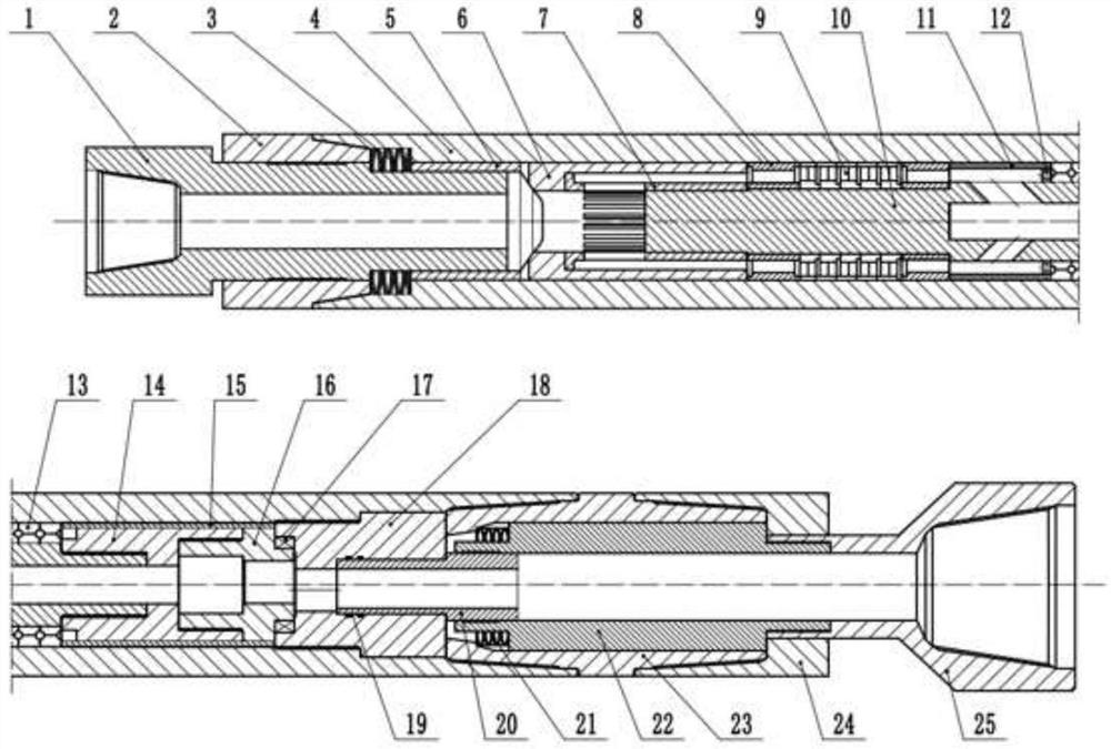
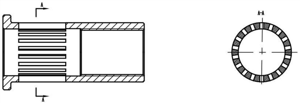
[0017] like Figure 1-5 As shown, an anti-jamming drilling speed-increasing tool, its structure mainly includes: sliding rod 1, upper joint 2, disc spring I 3, outer cylinder 4, force transmission sleeve 5, piston head cover 6, shunt element 7, rolling bearing 8. Turbine device 9, transmission shaft 10, adjustment ring 11, positioning cylinder 12, thrust bearing 13, transmission element 14, support cylinder 15, moving valve disc 16, bearing 17, fixed valve disc 18, sealing ring 19, valve disc Inner sleeve 20, disc spring II 21, hollow spindle 22, first lower shell 23, second lower shell 24, lower joint 25; its technical features are: upper joint 2, outer cylinder 4, first lower shell 23. The second lower housing 24 is threaded sequentially from top to bottom; the sliding rod 1 is installed in the inner hole of the upper joint 2 and the outer cylinder 4, and the clearance fits, and the sliding rod 1 and the upper joint 2 are connected by splines, sliding The lower end of the r...
PUM
Abstract
The invention relates to a tool for absorbing the impact on the drill bit, reducing the friction between the drill pipe and the well wall, and improving the drilling efficiency. The technical solution is: the anti-jamming drilling speed-up tool mainly includes: , upper joint, disc spring I, outer cylinder, force transmission sleeve, piston head cover, shunt element, rolling bearing, turbine device, transmission shaft, adjustment ring, positioning cylinder, thrust bearing, transmission element, support cylinder, moving valve disc , bearing, fixed valve disc, sealing ring, inner sleeve of valve disc, disc spring II, hollow mandrel, first lower shell, second lower shell, lower joint; when the drill bit is subjected to impact vibration or excessive torque, the compression The disc spring is lifted upwards to prevent drill sticking; driven by the transmission shaft, the eccentric fit between the two valve discs converts the liquid energy into pulse pressure and transmits it to the slide rod, so that the static friction between the drilling tool and the well wall is converted into dynamic friction .
Description
technical field [0001] The patent of the invention relates to the field of downhole tools in petroleum exploitation engineering, belongs to downhole auxiliary drilling equipment, and specifically relates to a drilling speed-increasing tool for preventing drill sticking and reducing the forward resistance of drill strings. Background technique [0002] With the continuous development of oil drilling technology, various drilling speed-increasing tools have been developed to meet the needs of different drilling projects. However, there are still many problems for the complex working environment downhole. And drill life has been a hot topic of research. [0003] In soft-hard formations or hard formations, harmful vibrations and shocks to the drill bit are likely to occur during drilling. These harmful vibrations and shocks not only affect the drilling rate, but also easily cause damage to the drill bit, and may even fail early, increasing drilling costs. [0004] Faced with the...
Claims
Application Information
Patent Timeline
Application Date:The date an application was filed.
Publication Date:The date a patent or application was officially published.
First Publication Date:The earliest publication date of a patent with the same application number.
Issue Date:Publication date of the patent grant document.
PCT Entry Date:The Entry date of PCT National Phase.
Estimated Expiry Date:The statutory expiry date of a patent right according to the Patent Law, and it is the longest term of protection that the patent right can achieve without the termination of the patent right due to other reasons(Term extension factor has been taken into account ).
Invalid Date:Actual expiry date is based on effective date or publication date of legal transaction data of invalid patent.