
Control system and method of impact type cutter head device

A technology of a control system and a control method, which is applied in earth-moving drilling, mining equipment, tunnels, etc., can solve problems such as impact equipment jamming, increasing the number of construction personnel, and slow rotating speed of the cutter head.

Active Publication Date: 2021-03-16
CHINA RAILWAY CONSTR HEAVY IND
View PDF7 Cites 0 Cited by
  • Summary
  • Abstract
  • Description
  • Claims
  • Application Information

AI Technical Summary

Problems solved by technology

[0002] With the rapid development of the underground engineering industry, the ensuing complexity of the rock formation structure, a single hob-type cutter head can no longer meet the construction needs, the new type of impact cutter head combined with impact crushing and rolling crushing is an important tool for underground engineering construction. A new direction is provided. The cutter head with the hob is a cutter head that rolls the rock formation radially at high linear speed, and the impact equipment impacts the rock formation axially. The cutter head rotates fast, the impact frequency of the impact equipment and Slow speed will lead to jamming of impact equipment, impact omission, etc., slow cutterhead speed, high impact frequency and speed of impact equipment will lead to empty strike of impact equipment
Most of the existing technologies separate the impact equipment and the rolling cutter head, and construct by breaking rocks in stages. This method reduces the efficiency of equipment use, increases the number of construction personnel, and affects the progress of construction.

Method used


Image

  • Control system and method of impact type cutter head device
  • Control system and method of impact type cutter head device
  • Control system and method of impact type cutter head device

Examples


Embodiment Construction

[0042] The following will clearly and completely describe the technical solutions in the embodiments of the present invention with reference to the accompanying drawings in the embodiments of the present invention. Obviously, the described embodiments are only some, not all, embodiments of the present invention. Based on the embodiments of the present invention, all other embodiments obtained by persons of ordinary skill in the art without making creative efforts belong to the protection scope of the present invention.

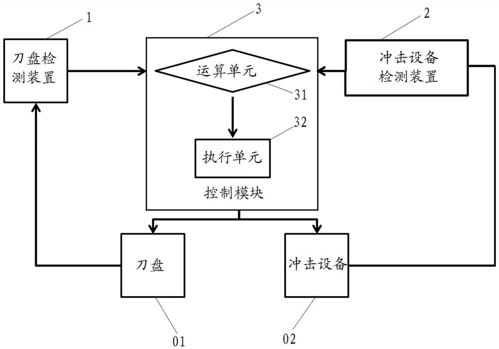
[0043] The core of the present invention is to provide a control system of the impact cutter head device, which can match the rotation speed of the cutter head and the impact frequency and rotation speed of the impact equipment synchronously, thereby ensuring continuous construction and improving work efficiency. Another core of the present invention is to provide a method applied to the control system of the above-mentioned impact cutter head device.

[0044]...


PUM


Abstract

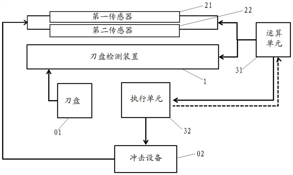
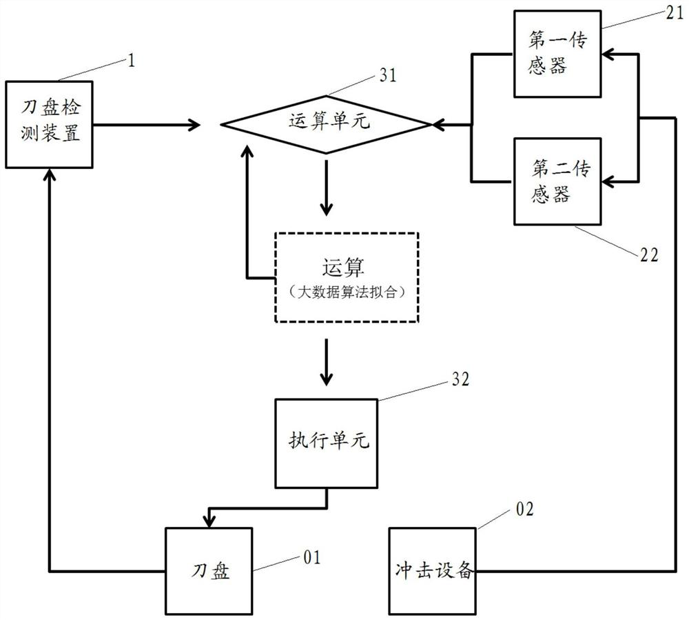
The invention discloses a control system and method of an impact type cutter head device. The control system comprises a cutter head detection device, an impact equipment detection device and a control module electrically connected with the cutter head detection device and the impact equipment detection device, wherein the cutter head detection device is used for detecting the rotating speed of acutter head; the impact equipment detection device is used for detecting the impact frequency and the rotating speed of impact equipment; and the control module is used for controlling the impact equipment or the cutter head according to the cutter head rotating speed detected by the cutter head detection device and the impact equipment impact frequency and the impact equipment rotating speed detected by the impact equipment detection device, so as to make the rotating speed of the cutter head to be matched with the impact frequency and the rotating speed of the impact equipment. According tothe control system and method, the rotating speed of the cutter head can be matched with the impact frequency and the rotating speed of the impact equipment so that the construction efficiency can begreatly improved, and the loss rate and the construction risk of the equipment are reduced.

Description

technical field [0001] The invention relates to the technical field of tunneling, in particular to a control system of an impact cutterhead device. The invention also relates to a method applied to the control system of the impact cutter head device. Background technique [0002] With the rapid development of the underground engineering industry, the ensuing complexity of the rock formation structure, a single hob-type cutter head can no longer meet the construction needs, the new type of impact cutter head combined with impact crushing and rolling crushing is an important tool for underground engineering construction. A new direction is provided. The cutter head with the hob is a cutter head that rolls the rock formation radially at high linear speed, and the impact equipment impacts the rock formation axially. The cutter head rotates fast, the impact frequency of the impact equipment and Slow speed will lead to jamming of impact equipment, impact omission, etc., slow cutt...

Claims


Application Information

Patent Timeline
IPC IPC(8): E21D9/10
CPCE21D9/108E21D9/1006E21D9/106
Inventor 刘飞香程永亮廖金军赵贵生蒋海华范文军易达云伍容孔文
Owner CHINA RAILWAY CONSTR HEAVY IND
Learn More