
Vibration reduction clamping type fixing device for mechanical equipment

A technology for mechanical equipment and fixing devices, which is applied in the field of vibration-damping clamp-mounted mechanical equipment fixing devices, can solve problems such as changes in the fixing strength of the fixing device, the inability to adjust the distance of the fixing device, and loose internal parts, etc., so as to increase practicability Effect

Inactive Publication Date: 2021-03-16
陆学顶
View PDF4 Cites 1 Cited by
  • Summary
  • Abstract
  • Description
  • Claims
  • Application Information

AI Technical Summary

Problems solved by technology

[0002] When general mechanical equipment is working, the mechanical equipment will vibrate due to the force generated by the operation of the internal parts. Long-term vibration will not only easily loosen the internal parts, but also cause the mechanical equipment to shift. Parts are inspected and fastened, and the offset mechanical equipment needs to be moved to the original position, which undoubtedly increases the workload of the staff
[0003] The usual mechanical equipment fixing device can achieve buffering and vibration reduction by installing some elastic equipment, but the fixing strength of the fixing device cannot be changed according to the change of the vibration intensity, and the fixing device cannot realize the adjustment of the distance. The fixed mechanical equipment is single, which cannot meet the current requirements. mechanical equipment needs

Method used


Image

  • Vibration reduction clamping type fixing device for mechanical equipment
  • Vibration reduction clamping type fixing device for mechanical equipment
  • Vibration reduction clamping type fixing device for mechanical equipment

Examples


Embodiment 1

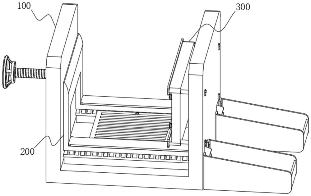
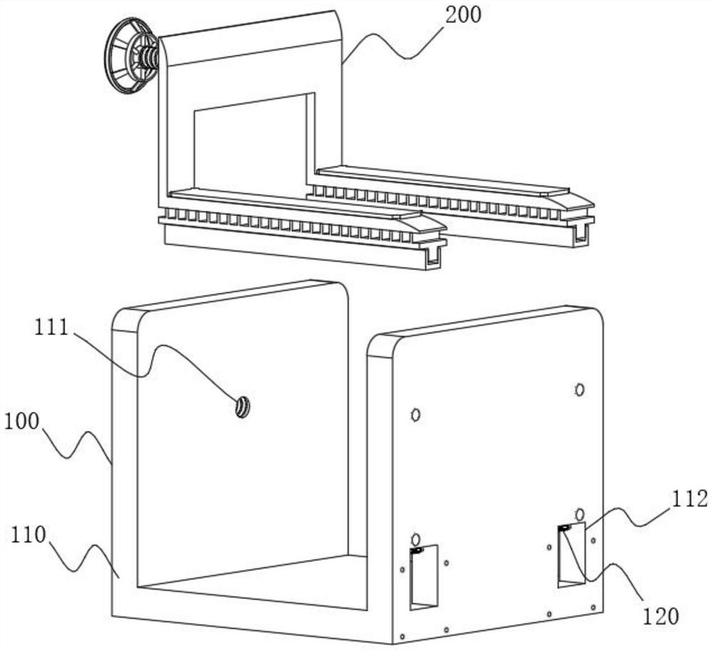
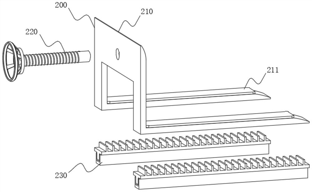
[0073] The present invention provides a vibration-damping clamp-mounted mechanical equipment fixing device, please refer to Figure 1-Figure 14 , including a supporting device 100, a distance adjusting device 200 and a vibration-damping clamping device 300 arranged on the opposite side of the distance adjusting device 200, the supporting device 100 includes a supporting frame 110, and the supporting frame 110 is a "U"-shaped plate, through which the supporting frame The left side wall of 110 supports the movable plate 310, and its right side wall supports the adjustment frame 210. The distance adjustment device 200 includes the adjustment frame 210. The adjustment frame 210 is an "L" shaped plate, and the bottom is hollowed out, forming two A placement plate with a width smaller than the right side wall of the adjustment frame 210, thereby reducing the area of ​​the reserved groove 112 on the left side wall of the support frame 110, reducing the hollowing degree of the left sid...


PUM


Abstract

The invention relates to a fixing device for mechanical equipment, in particular to a vibration reduction clamping type fixing device for the mechanical equipment. The device comprises a supporting device, a distance adjusting device and a vibration reduction clamping device arranged on the side opposite to the distance adjusting device, wherein the supporting device comprises a supporting frame,the distance adjusting device comprises an adjusting frame, the adjusting frame is an L-shaped plate, the bottom of the adjusting frame is in a hollowed-out state, and two containing plates with the width smaller than that of the right side wall of the adjusting frame are formed, and the middle of the right side wall of the adjusting frame is rotationally connected with a lead screw. According tothe device, the mechanical equipment is further pressed through an arranged pre-tightening rod, the larger the shaking strength of the mechanical equipment is, the smaller the compression space is, the larger the pressure is, and the higher the further pressing strength is, so that the pre-tightening effect is achieved when the mechanical equipment shakes, and meanwhile, the change of the pressingstrength is achieved, and therefore the fixing stability of a clamping plate is further improved.

Description

technical field [0001] The invention relates to a fixing device for mechanical equipment, in particular to a vibration-damping clamp-mounted fixing device for mechanical equipment. Background technique [0002] When general mechanical equipment is working, the mechanical equipment will vibrate due to the force generated by the operation of the internal parts. Long-term vibration will not only easily loosen the internal parts, but also cause the mechanical equipment to shift. Parts are inspected and fastened, and the offset mechanical equipment needs to be moved to the original position, which undoubtedly increases the workload of the staff. [0003] The usual mechanical equipment fixing device can achieve buffering and vibration reduction by installing some elastic equipment, but the fixing strength of the fixing device cannot be changed according to the change of the vibration intensity, and the fixing device cannot realize the adjustment of the distance. The fixed mechanic...

Claims


Application Information

Patent Timeline
Patent Type & Authority Applications(China)
IPC IPC(8): F16M11/04F16M11/22F16F15/067F25D31/00
CPCF16M11/04F16M11/22F16F15/067F25D31/002F16F2238/026
Inventor 陆学顶
Owner 陆学顶
Learn More