
Cooling injection water drainage control method and system

A water for injection and control method technology, applied in the pipeline system, pipeline heating/cooling, heat preservation, etc., can solve the problems of large consumption of high-temperature water for injection, increase of production cost, waste of high-temperature water for injection, etc., to improve the timeliness of shutdown, The effect of reducing production costs and reducing the chance of waste

Pending Publication Date: 2021-03-16
YANGTZE RIVER PHARM GRP GUANGZHOU HAIRUI PHARM CO LTD
View PDF6 Cites 0 Cited by
  • Summary
  • Abstract
  • Description
  • Claims
  • Application Information

AI Technical Summary

Problems solved by technology

[0004] However, in the traditional water for injection circulation system, the valve is closed at the water outlet of the cooling outlet pipe by manual closing, and the manual closing of the valve usually has two situations, one is to close the valve too early, This will cause the cooled water for injection to return to the circulation system of high-temperature water for injection, which will affect the temperature in the circulation system of high-temperature water for injection, thus causing damage to the circulation system of high-temperature water for injection; and the other is to close the valve too late , which leads to the excessive use of high-temperature water for injection before the cooling water for injection is completely squeezed out, resulting in waste of high-temperature water for injection and increased production costs

Method used


Image

  • Cooling injection water drainage control method and system
  • Cooling injection water drainage control method and system
  • Cooling injection water drainage control method and system

Examples


Embodiment Construction

[0023] In order to facilitate the understanding of the present invention, the present invention will be described more fully below with reference to the associated drawings. Preferred embodiments of the invention are shown in the accompanying drawings. However, the present invention can be embodied in many different forms and is not limited to the embodiments described herein. On the contrary, the purpose of providing these embodiments is to make the disclosure of the present invention more thorough and comprehensive.

[0024] It should be noted that when an element is referred to as being “fixed” to another element, it can be directly on the other element or there can also be an intervening element. When an element is referred to as being "connected to" another element, it can be directly connected to the other element or intervening elements may also be present. The terms "vertical," "horizontal," "left," "right," and similar expressions are used herein for purposes of ill...


PUM


Abstract

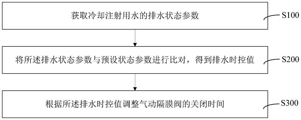
The invention provides a cooling injection water drainage control method and system. The cooling injection water drainage control method comprises the steps that drainage state parameters of cooling injection water are obtained; the drainage state parameters are compared with a preset state parameter to obtain a drainage time control value; and closing time of a pneumatic diaphragm valve is adjusted according to the drainage time control value. By acquiring the drainage state parameters, namely acquiring a current drainage state of the cooling injection water, the drainage condition of the cooling injection water can be conveniently acquired after the drainage time control value is acquired, that is, complete drainage time of the cooling injection water and water outlet closing time of thecooling injection water can be conveniently acquired, the pneumatic diaphragm valve is closed in time according to the drainage time control value, so that a use amount of injection water in a high-temperature state for completely draining the cooling injection water is reduced, closing timeliness of the pneumatic diaphragm valve is improved, the waste probability of the injection water in the high-temperature state is reduced, and the production cost is reduced.

Description

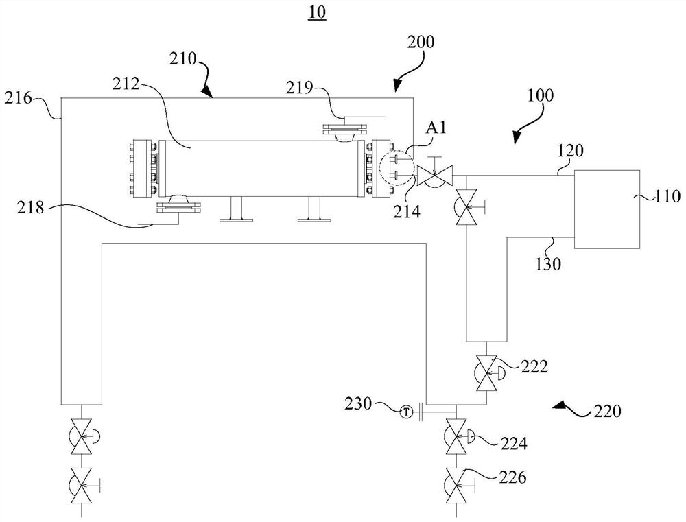
technical field [0001] The invention relates to the technical field of water for injection, in particular to a method and system for controlling drainage of cooling water for injection. Background technique [0002] With the widespread use of water for injection in pharmaceutical production and medical care, water for injection is used as a mainstream pharmaceutical solvent, and there are strict production standards for the production of water for injection. Because water for injection has the effect of high-temperature sterilization, it is more and more favored by the pharmaceutical manufacturing industry. [0003] In the traditional circulation system for producing water for injection, the temperature of water for injection is the medium circulated by high-temperature pipelines. During production, it is necessary to use cooled water for injection to avoid the temperature of the medicine to be dissolved exceeding the failure temperature, thereby reducing the failure rate of...

Claims


Application Information

Patent Timeline
IPC IPC(8): F17D1/08F17D3/01F17D5/00F17D5/02F16L53/70F16L55/07F16L59/02
CPCF17D1/08F17D3/01F17D5/00F17D5/02F16L59/02F16L53/70F16L55/07
Inventor 徐磊卢盛宝梁祥耀白颜宁
Owner YANGTZE RIVER PHARM GRP GUANGZHOU HAIRUI PHARM CO LTD
Learn More