Fluorescence spectrum-based transformer fault diagnosis device and method

A transformer fault and fluorescence spectrum technology, applied in the direction of fluorescence/phosphorescence, measuring devices, instruments, etc., can solve the problems of unable to systematically reflect the state and operation status of transformer oil, long test and analysis cycle, long test cycle, etc., to achieve improvement Unstable clustering results, strong anti-electromagnetic interference ability, and reduced modeling time

Pending Publication Date: 2021-03-16
ANHUI UNIV OF SCI & TECH
View PDF6 Cites 2 Cited by
  • Summary
  • Abstract
  • Description
  • Claims
  • Application Information

AI Technical Summary

Benefits of technology

This new method described in this patented allows for faster and easier analysis of electrical equipment's health condition based on its own characteristics such as temperature or pressure levels during use. By applying lasers onto specific areas of an electric device without any extra steps like separating gases before testing it, these methods are able to identify potential issues early enough that they may have already been damaged. Additionally, there exist various techniques used to reduce redundancy in spectral datasets obtained from different measurements made over multiple periods of observation (such as Fourier Transform) resulting in better overall performance compared to previous models. Overall, this innovation provides technical benefits including quick and precise diagnoses of power failings, increased recognition rates through advanced machine learning algorithms, reduced complexity due to fewer featured layers, enhanced reliability, etc., making them ideal tools for identifying important components within large complex systems containing many interconnected parts.

Problems solved by technology

The technical problem addressed in this patents relates to identifying faulty or damaged transformers during maintenance operations without human error while ensuring proper functioning of electric grids. Current solutions involve manually inspecting each unit individually, leading to delayed diagnoses due to fatigue and lack reliability. There have been attempts at developing faster and better ways to monitor these assets safely before they fail catastrophically.

Method used


Image

  • Fluorescence spectrum-based transformer fault diagnosis device and method
  • Fluorescence spectrum-based transformer fault diagnosis device and method
  • Fluorescence spectrum-based transformer fault diagnosis device and method

Examples


Embodiment Construction

[0052] The present invention will be further explained below through specific embodiments and with reference to the accompanying drawings, so that the advantages and features of the present invention can be more easily understood by those skilled in the art, so that the protection scope of the present invention can be defined more clearly.

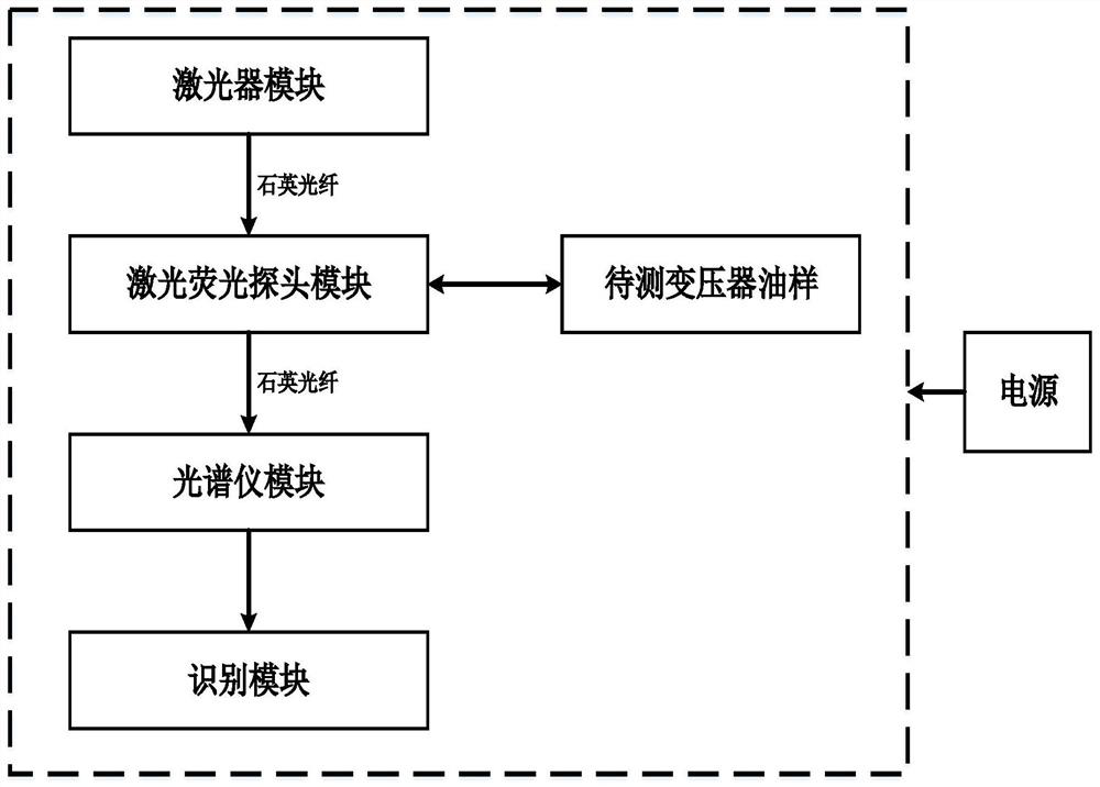
[0053] see figure 1 , the embodiment of the present invention includes:

[0054] Provide a transformer fault diagnosis device based on fluorescence spectrum, the device includes a power module, a laser module connected to the power module, a laser fluorescence probe module, a spectrometer module, an identification module, one end of the submerged miniature fluorescence probe passes through a UV / VIS quartz optical fiber It is connected to the laser module, the other end is connected to the spectrometer module through UV / VIS quartz fiber, and finally the USB2000+ personalized configuration spectrometer is connected to the host computer.

[...


PUM


Abstract

The invention provides a fluorescence spectrum-based transformer fault diagnosis device, which comprises a power supply module, a laser module, a laser fluorescence probe module, a spectrograph moduleand an identification module. The invention further discloses a fluorescence spectrum-based transformer fault diagnosis method, which comprises the following steps of: (1) collecting an oil sample and establishing a spectrum database; (2) filtering the original spectrum; (3) performing feature extraction on the spectral data of the transformer oil sample; (4) randomly dividing the spectral data into a training set and a test set according to a ratio of 5: 1; (5) establishing a GMM-LDA identification model, and applying the test set to model inspection and identification; and (6) carrying outtransformer fault diagnosis. An LIF technology is combined with a DAE-GMM-LDA method to analyze the state of the transformer oil so as to achieve transformer fault diagnosis, the classification and recognition accuracy and practical application value are high, the generalization capacity is high, and the device and the method are quite suitable for real-time and accurate transformer fault detection and diagnosis and popularization.

Description


Claims


Application Information

Patent Timeline
Owner ANHUI UNIV OF SCI & TECH
Why Eureka
Try Eureka