Attaching jig and attaching method for light guide plate and reflector plate, and backlight module

A technology of backlight modules and reflectors, applied in light guides, optics, optical components, etc., can solve problems such as low production efficiency, substandard optics, and low precision, achieve fast attachment speed, reduce labor waste, and improve production efficiency effect

Pending Publication Date: 2021-03-16
深圳市隆利光电科技发展有限公司
View PDF5 Cites 2 Cited by
  • Summary
  • Abstract
  • Description
  • Claims
  • Application Information

AI Technical Summary

Problems solved by technology

[0007] The invention discloses a fixture for attaching a light guide plate and a reflection sheet, an attachment method, and a backlight module, which are used to solve the problems in the prior art that the accuracy of manually attaching a light guide plate and a reflection sheet is low, and the optics are not up to standard. Low production efficiency and waste of manpower

Method used


Image

  • Attaching jig and attaching method for light guide plate and reflector plate, and backlight module
  • Attaching jig and attaching method for light guide plate and reflector plate, and backlight module
  • Attaching jig and attaching method for light guide plate and reflector plate, and backlight module

Examples


Embodiment 1

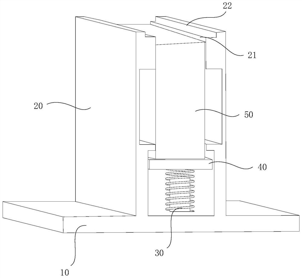
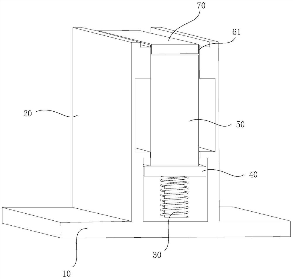
[0042] Such as Figure 1~4 As shown, the fixture for attaching the light guide plate and the reflection sheet provided by the present invention includes a fixture body, the fixture body is provided with a forming part 21 and a supporting part 22, the supporting part 22 is arranged above the forming part 21, and the supporting part 22 The size of the molding part 21 is greater than the size of the molding part 21. The size of the molding part 21 is adapted to the size of the light guide plate 70. The size of the support part 22 is adapted to the size of the preformed reflective sheet 60. After the light guide plate 70 and the preformed reflective sheet 60 are When stacked on the support part 22, by pressing the light guide plate 70 or the preformed reflective sheet 60, the light guide plate 70 and the preformed reflective sheet 60 are pressed from the support part 22 to the molding part 21, and the preformed reflective sheet 60 is formed into a shaped reflective sheet. The shee...

Embodiment 2

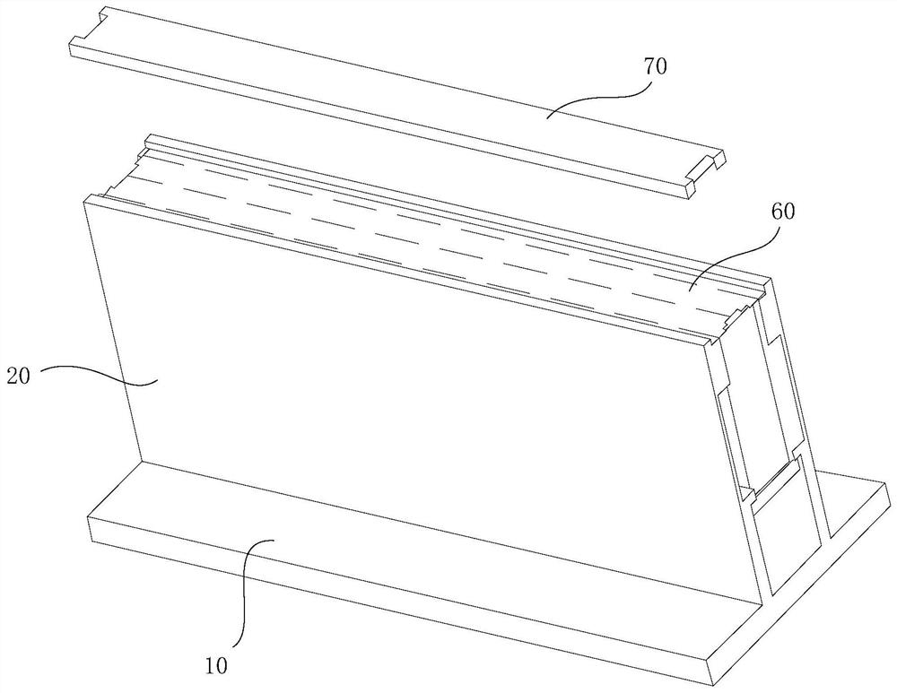
[0048] Utilize the attachment method of the light guide plate of embodiment 1 and the attachment fixture of reflective sheet, combine Figure 5 shown, including:

[0049] Set pre-breaking lines on the other three sides of the preformed reflector 60 except the side close to the light source;

[0050] stacking the preformed reflective sheet 60 and the light guide plate 70 on the supporting part 22;

[0051] Press the light guide plate 70 or the preformed reflective sheet 60, and press the light guide plate 70 and the preformed reflective sheet 60 from the supporting part 22 to the forming part 21;

[0052] The preformed reflective sheet 60 is formed such that the shaped reflective sheet 61 is attached to the light guide plate 70 .

[0053] In this embodiment, a mechanical arm is used to grab the preformed reflective sheet 60 and the light guide plate 70, and place them on the support part 22, and press the light guide plate 70 and the preformed reflective sheet 60 from the sup...

Embodiment 3

[0055] The difference from Embodiment 2 is that in this embodiment, the light guide plate 70 and the preformed reflective sheet 60 are manually placed on the attachment jig and manually pressed and bonded, without other mechanical equipment.


PUM


Abstract

The invention discloses an attaching jig and an attaching method for a light guide plate and a reflector plate, and a backlight module. The attaching jig comprises a jig body, the jig body is providedwith a forming part and a supporting part, the supporting part is arranged above the forming part, the size of the supporting part is larger than that of the forming part, the size of the forming part is matched with that of a light guide plate, and the size of the supporting part is matched with the size of a preformed reflector plate. When the light guide plate and the preformed reflector plateare stacked on the supporting part, the light guide plate and the preformed reflector plate are pressed to the forming part from the supporting part by pressing the light guide plate or the preformedreflector plate, and the preformed reflector plate is formed into a formed reflector plate and attached to the light guide plate. The attaching jig is adopted for attaching the light guide plate andthe reflector plate, accurate attaching can be achieved, it is guaranteed that the light guide plate and the reflector plate are completely attached, the reliability of the backlight module is improved, the attaching speed is high, the production efficiency is improved, and manpower waste is reduced.

Description

technical field [0001] The invention relates to the technical field of assembly jigs for backlight modules, in particular to a jig for attaching a light guide plate and a reflection sheet, an attachment method, and a backlight module. Background technique [0002] With the development of science and technology, the application fields of backlights are becoming wider and wider, and the production and manufacturing of backlights are booming. In the design, the brightness is often insufficient, and reflective strips are often pasted on the side of the light guide plate to increase the brightness of the backlight. The traditional way of working is to attach it by hand. First, fold the two sides of the reflective sheet in half along the seam line to the direction of the double-sided adhesive surface by hand, so that the reflective sheet of the wrapping part and the part of the ground reflective sheet can keep the bending memory. Then tear off the reflective release base film, ali...

Claims


Application Information

Patent Timeline
Patent Type & Authority Applications(China)
IPC IPC(8): G02B6/00
CPCG02B6/0055G02B6/0065
Inventor 张安福梁子顺韦天初
Owner 深圳市隆利光电科技发展有限公司
Why Eureka
Try Eureka