Multifunctional motor stator part machining device

A technology for motor stators and processing devices, which is applied in the manufacture of stator/rotor bodies, etc., can solve problems such as low production efficiency, waste of manual labor, and disordered arrangement of copper wires, and achieve the effect of improving production efficiency

Inactive Publication Date: 2021-03-19
补建伟
View PDF0 Cites 1 Cited by
  • Summary
  • Abstract
  • Description
  • Claims
  • Application Information

AI Technical Summary

Problems solved by technology

[0003] When processing the stator parts of the motor, the parts need to enter the extrusion equipment at the set position, and the extrusion equipment extends into the interior of the motor stator to extrude the stator windings of the motor stator, but some extrusion equipment is based on The size of the inner diameter of the stator part of the motor is designed, and only the stator winding of the same type of motor stator part can be extruded, and the extrusion equipment is cylindrical. During the extrusion process, the stator winding is easily affected by the uneven arrangement of the copper wires caused by the pressure. A rotating magnetic field is generated. In addition, when the motor stator parts are placed in the set position, it is generally necessary to manually support the motor stator parts, which not only wastes a lot of manual labor, but also has low production efficiency.

Method used


Image

  • Multifunctional motor stator part machining device
  • Multifunctional motor stator part machining device
  • Multifunctional motor stator part machining device

Examples


Embodiment Construction

[0024] The technical solutions in the embodiments of the present invention will be clearly and completely described below in conjunction with the embodiments of the present invention. Apparently, the described embodiments are only some of the embodiments of the present invention, not all of them. Based on the embodiments of the present invention, all other embodiments obtained by persons of ordinary skill in the art without creative efforts fall within the protection scope of the present invention.

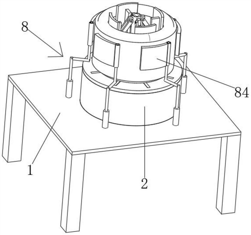
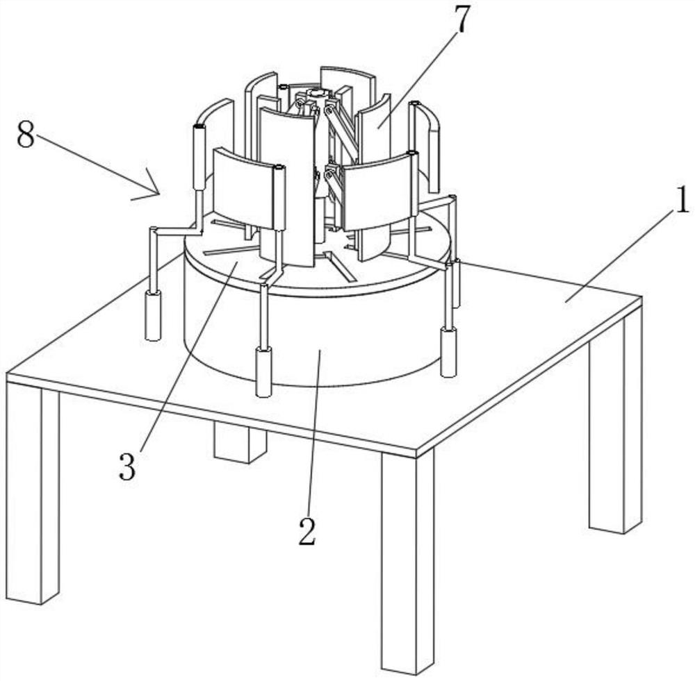
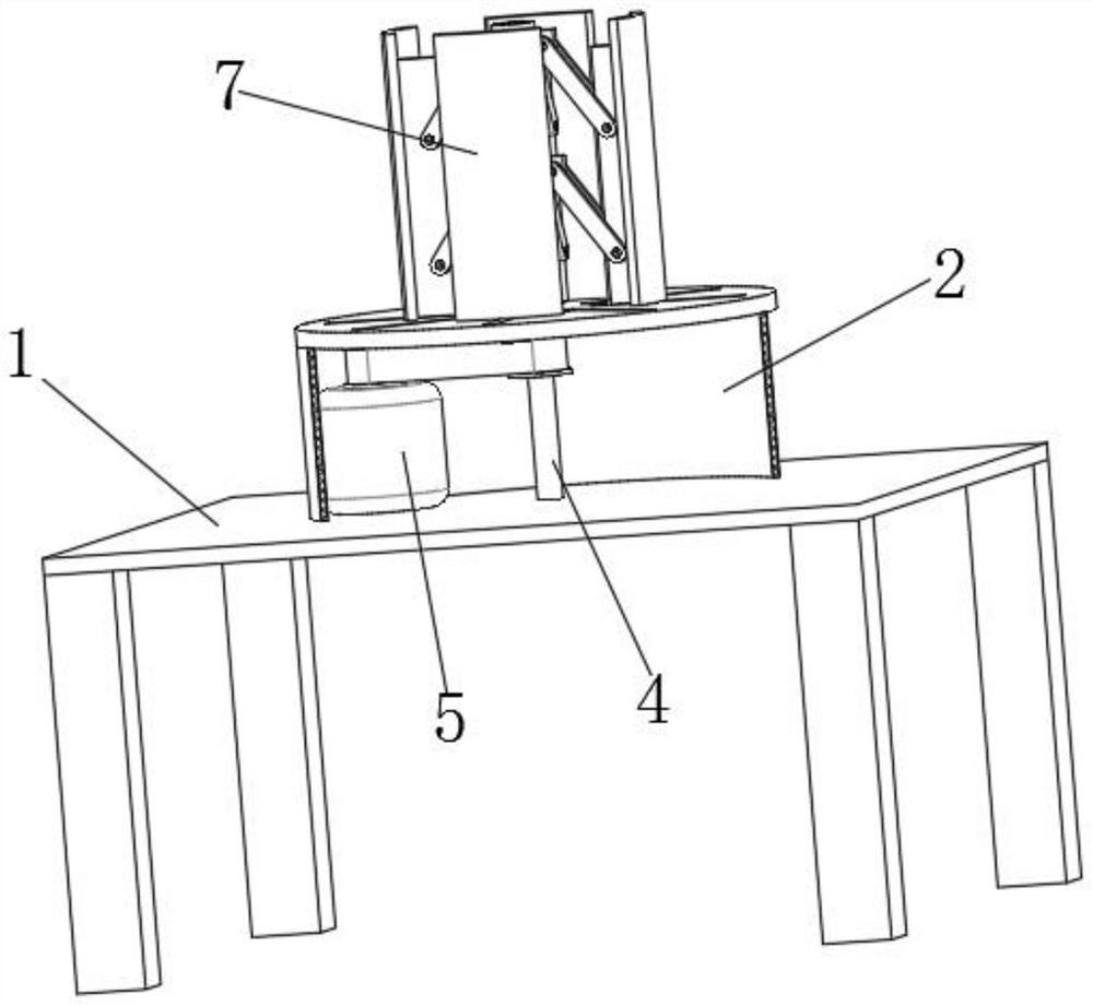
[0025] see Figure 1-7 As shown, a multifunctional motor stator component processing device includes a console 1, the top surface of the console 1 is fixedly connected with an annular support seat 2, the top surface of the annular support seat 2 is fixedly connected with a circular base 3, and the circular base The top surface of 3 has a plurality of limit holes 31 in a circular and equiangular shape. The top surface of the console 1 is rotatably connected with a shaft 4. The top ...


PUM


Abstract

The invention relates to the technical field of motor stator machining equipment, in particular to a multifunctional motor stator part machining device. The device comprises an operation table, an annular supporting base is fixedly connected to the top face of the operation table, a circular base is fixedly connected to the top face of the annular supporting base, a plurality of limiting holes areannularly formed in the top face of the circular base at equal angles, a shaft rod is rotatably connected to the top face of the operation table, the top of the shaft rod penetrates through the circular base and is fixedly connected with an air cylinder, the outer side wall of the top of the shaft rod is movably sleeved with a sleeve, and the top of the sleeve is fixedly connected with the outputend of the air cylinder. The output end of the air cylinder moves downwards to drive the sleeve to move downwards, connecting rods around the sleeve are gradually unfolded in the direction away fromthe shaft rod at the moment, the connecting rods push an extrusion plate to move in the direction away from the shaft rod, the extrusion plate extrudes the inner side wall of a motor stator part, uniform extrusion of a stator winding is achieved, and the production efficiency of the motor stator part is improved.

Description

technical field [0001] The invention relates to the technical field of motor stator processing equipment, in particular to a multifunctional motor stator component processing device. Background technique [0002] Silicon steel sheet is a kind of silicon-iron soft magnetic alloy with extremely low carbon content. Generally, the silicon content is 0.5-4.5%. Loss) and magnetic aging, its resistivity and maximum point permeability are high, usually used to make transformers, motors, motor cores, motor stator parts are generally extruded T-shaped silicon steel sheets, so that the silicon steel sheets The lock is fastened and formed. The motor stator is composed of three parts: the stator core, the stator winding and the machine base. The main function of the motor stator is to generate a rotating magnetic field, and the main function of the rotor is to be cut by the magnetic force lines in the rotating magnetic field to generate (output) current; [0003] When processing the st...

Claims


Application Information

Patent Timeline
IPC IPC(8): B21C23/14B21C23/21H02K15/02
CPCB21C23/14B21C23/21H02K15/02
Inventor 补建伟
Owner 补建伟
Why Eureka
Try Eureka