Honing head capable of achieving single-double feeding and hole diameter adjusting for cylinder body and cylinder sleeve

A honing head and cylinder block technology, applied in the field of cylinder block honing, can solve problems such as unfavorable economic benefits, affecting processing efficiency, and large workload

Active Publication Date: 2021-03-19
郑州宏拓精密工具有限公司
View PDF8 Cites 3 Cited by
  • Summary
  • Abstract
  • Description
  • Claims
  • Application Information

AI Technical Summary

Problems solved by technology

[0005] In the process of switching the workpiece from rough grinding to fine grinding, a large amount of manual participation is required to realize the control of the honing process. The whole process has a low degree of automation, which affects the processing efficiency and also brings a greater burden to the staff. The workload is not conducive to the maximization of economic benefits;

Method used


Image

  • Honing head capable of achieving single-double feeding and hole diameter adjusting for cylinder body and cylinder sleeve
  • Honing head capable of achieving single-double feeding and hole diameter adjusting for cylinder body and cylinder sleeve
  • Honing head capable of achieving single-double feeding and hole diameter adjusting for cylinder body and cylinder sleeve

Examples


Embodiment 1

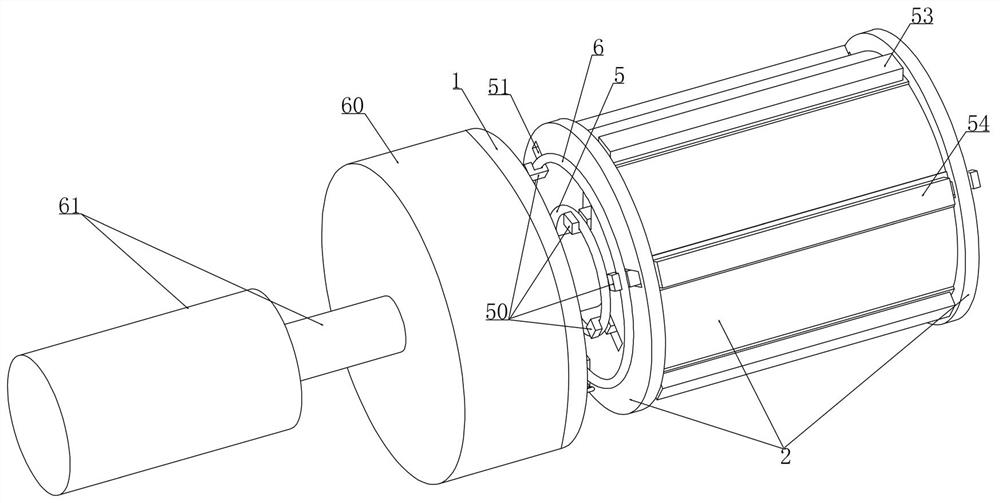
[0042] Embodiment 1, this embodiment provides a honing head with single and double feed for cylinder block and cylinder liner and adjustable hole diameter, refer to the attached figure 1 As shown, including the bearing plate 1, we rotate the bearing cylinder 2 on the bearing plate 1 and we are integrally provided with a sealing cylinder 60 on the bearing plate 1, and the sealing cylinder 60 is driven by a reciprocating push rod 61 (the reciprocating push The rod 61 can be an electric push rod 43), that is, the carrying cylinder 2 moves linearly and reciprocatingly under the action of the reciprocating push rod 61. The fine grinding base 3 and coarse grinding base 4 refer to the attached figure 1 As shown, several fine grinding bases 3 and coarse grinding bases 4 extend along the length direction of the bearing cylinder 2, and we make several fine grinding bases 3 and coarse grinding bases 4 alternately set up when setting (that is, make the fine grinding bases 3 and coarse gr...

Embodiment 2

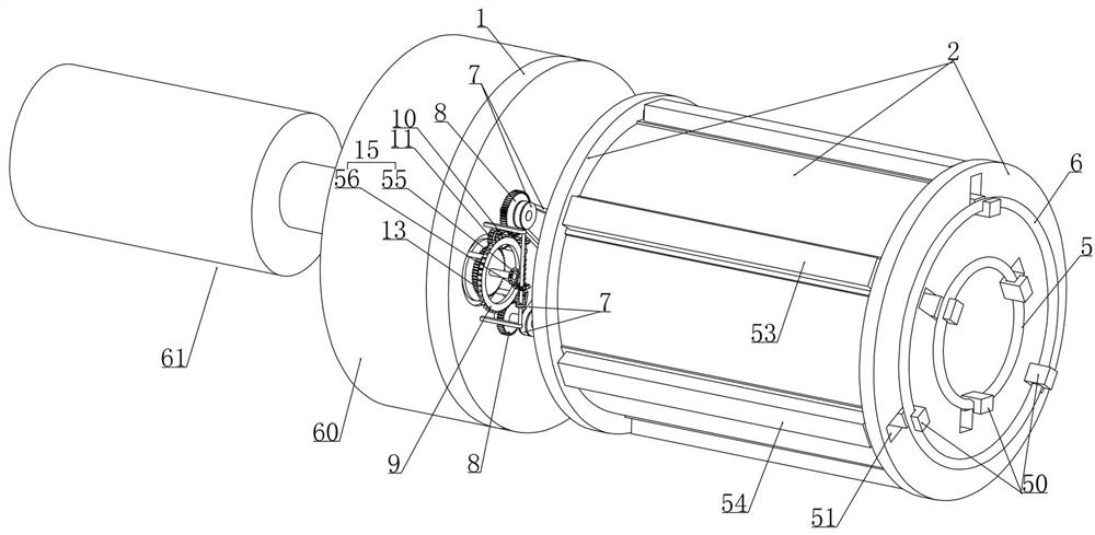
[0048] Embodiment 2, on the basis of embodiment 1, with reference to appended Figure 9 As shown, the drive switching device includes a worm gear ring 9 rotatably mounted on the lower end surface of the bearing plate 1, referring to the attached Figure 11 As shown, we rotate and install a rotating shaft 12 on the upper end of the worm wheel ring 9, and the first gear 10 that is inherently matched with the two transmission gears 8 is placed on the rotating shaft 12. One-way gear 11, the one-way gear 11 meshes with the driving gear 13 that is rotatably mounted on the bearing plate 1. When we set it up, the centers of the two transmission gears 8 are distributed on a circle with the center of the driving gear 13 as the center and different diameters. (the distance between the center of circle of the larger transmission gear 8 of diameter and the center of circle of driving gear 13 is greater than the distance between the circle of the smaller transmission gear 8 of diameter and ...

Embodiment 3

[0054] Embodiment 3, on the basis of embodiment 1, with reference to appended Figure 13 As shown, we set a cylinder 18 coaxially in the bearing cylinder 2 and the bearing cylinder 2 is installed on the bearing plate 1 through the rotation of the cylinder 18, and the first belt drive 7 and the cylinder 18 pass through one end of the bearing cylinder 2 upwards. Connected, the radial push device includes a first push rod 19 coaxially arranged in the bearing cylinder 2 and axially slidingly fitted with the cylinder 18, refer to the attached Figure 14 As shown, the first push rod 19 passes through the bearing cylinder 2 at intervals upward (the first push rod 19 does not contact the bearing cylinder 2) and one end of the penetration is connected with the lifting mechanism. Refer to the attached Figure 15 As shown, we installed a second push cylinder 20 axially sliding on the outer wall of the cylinder 18, and we installed a number of precision grinding extrusion devices on the o...


PUM


Abstract

The invention relates to a honing head capable of achieving single-double feeding and hole diameter adjusting for a cylinder body and a cylinder sleeve. The honing head effectively solves the problemsthat an existing honing head is low in automation degree and single in function. According to the technical scheme, the honing head is provided with a fine grinding sand strip and a coarse grinding sand strip at the same time, specifically, the honing head can sequentially complete coarse grinding and fine grinding procedures on a workpiece under the condition that the sand strip does not need tobe replaced, the rotating speed of the honing head can be automatically adjusted after the honing head completes coarse grinding on the workpiece, and when the rotating speed of the honing head is adjusted, the rough grinding sand strip is synchronously moved away from a station, the fine grinding sand strip is synchronously moved to the corresponding station, the whole honing process is highly automatic, excessive manual participation is not needed, the machining efficiency is greatly improved, and meanwhile the workload of workers is relieved.

Description

technical field [0001] The invention relates to the technical field of cylinder block honing, in particular to a honing head with single and double feeding for cylinder blocks and cylinder sleeves and adjustable hole diameter. Background technique [0002] In industrial production, a honing machine is a grinding machine that uses a honing head to honed the surface of a workpiece. It is mainly used for honing workpiece holes in manufacturing industries such as automobiles, tractors, hydraulic parts, bearings, and aviation. The honing machine is a precision manufacturing equipment. When the honing machine is grinding the holes of workpieces such as cylinder blocks and cylinder liners It is divided into two steps: rough grinding and fine grinding. During the rough grinding process, the abrasive bar of the honing head consumes a large amount of knife, but the spindle speed needs to be low. After the rough grinding is completed, the fine grinding is carried out. The cutting amou...

Claims


Application Information

Patent Timeline
Patent Type & Authority Applications(China)
IPC IPC(8): B24B33/02B24B33/08B24B33/10
CPCB24B33/02B24B33/105B24B33/083B24B33/10
Inventor 李巍耿忠忠吴博
Owner 郑州宏拓精密工具有限公司
Why Eureka
Try Eureka