Cylinder clamping device and mounting and using method thereof

A clamping device and cylinder technology, applied in vices, manufacturing tools, etc., can solve the problems of easy cracking and difficult clamping of cylinders, so as to improve stability, simple assembly method, and improve operation or maintenance efficiency. Effect

Pending Publication Date: 2021-03-19
GUANGDONG HONGTU TECHNOLOGY (HOLDINGS) CO LTD
View PDF5 Cites 1 Cited by
  • Summary
  • Abstract
  • Description
  • Claims
  • Application Information

AI Technical Summary

Problems solved by technology

[0005] In view of the above defects or improvement needs of the prior art, the present invention provides a cylinder clamping device and its installation and use method, which solves the situation that the traditional cast

Method used


Image

  • Cylinder clamping device and mounting and using method thereof
  • Cylinder clamping device and mounting and using method thereof
  • Cylinder clamping device and mounting and using method thereof

Examples


Embodiment Construction

[0041] In order to make the object, technical solution and advantages of the present invention clearer, the present invention will be further described in detail below in conjunction with the accompanying drawings and embodiments. It should be understood that the specific embodiments described here are only used to explain the present invention, not to limit the present invention. In addition, the technical features involved in the various embodiments of the present invention described below can be combined with each other as long as they do not constitute a conflict with each other.

[0042] In describing the present invention, it should be understood that the terms "center", "longitudinal", "transverse", "length", "width", "thickness", "upper", "lower", "front", " Back", "Left", "Right", "Vertical", "Horizontal", "Top", "Bottom", "Inner", "Outer", "Clockwise", "Counterclockwise", "Axial" , "radial", "circumferential" and other indicated orientations or positional relationsh...


PUM


Abstract

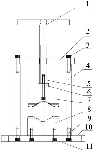
The invention discloses a cylinder clamping device. The device comprises a top plate, a bottom plate and several connecting rods arranged between the top plate and the bottom plate. The top plate is provided with external threads for a threaded rotating rod to pass therethrough, the bottom end of the threaded rotating rod is provided with an upper jaw clamp, and the upper jaw clamp is arranged corresponding to a lower jaw clamp fixed to the bottom plate. Grooves are formed in the front face of the upper jaw clamp and the front face of the lower jaw clamp to form corresponding first clamping openings, grooves are also formed in the side faces of the upper jaw clamp and the lower jaw clamp to form corresponding second clamping openings, lifting of the upper jaw clamp is achieved through rotation of the threaded rotating rod, and therefore clamping and loosening of a workpiece are achieved. The invention further discloses a mounting and using method of the cylinder clamping device. By means of the cylinder clamping device, the problem that a traditional cast iron vise is difficult to clamp a cylinder which is prone to cracking under stress is solved, the stability of clamping the cylinder is greatly improved, and the operation or maintenance efficiency of a cylindrical workpiece is improved.

Description

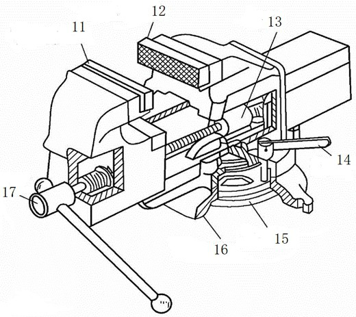
technical field [0001] The invention belongs to the technical field of clamping devices, and more particularly relates to a cylinder clamping device and its installation and use methods. Background technique [0002] The bench vise in the prior art is a universal fixture for clamping workpieces. The device is installed on a workbench to clamp and stabilize workpieces, and is an essential tool in a fitter's workshop. The turntable-type pliers can rotate to make the workpiece rotate to a suitable working position. [0003] The structure of the bench vise is as follows figure 1 As shown, it mainly includes movable jaw 11, fixed jaw 12, nut 13, clamping handle 14, clamping disc 15, turntable seat 16 and lead screw, etc. Cooperate, the lead screw 17 is installed on the movable pliers, which can rotate but cannot move axially, and cooperates with the nut 13 installed on the fixed pliers. When the clamping handle 14 is shaken to rotate the lead screw, the movable pliers can be dr...

Claims


Application Information

Patent Timeline
IPC IPC(8): B25B1/02B25B1/20
CPCB25B1/02B25B1/205
Inventor 甘海波吴焕宗徐世裕李绍华李家超郑文翔
Owner GUANGDONG HONGTU TECHNOLOGY (HOLDINGS) CO LTD
Why Eureka
Try Eureka