Self-sealing manhole cover plate dismounting tool for power station container equipment

A technology for manhole cover and container equipment, applied in the field of mechanical design, can solve the problem that the manhole cover cannot be accurately aligned with the sealing surface, the manhole cover collides with the sealing surface of the equipment, and the disassembly and assembly of the manhole cover is difficult. Large and other problems, to achieve the effect of improving stability and reliability, light weight and easy assembly

Pending Publication Date: 2021-03-19
JIANGSU NUCLEAR POWER CORP
View PDF0 Cites 2 Cited by
  • Summary
  • Abstract
  • Description
  • Claims
  • Application Information

AI Technical Summary

Problems solved by technology

[0002] Each unit of Tianwan NPP Phase III has 4 high-pressure heaters. The manhole cover of the equipment adopts a self-sealing type, and the sealing performance is improved compared with the traditional sealing structure. However, the disassembly process of the manhole cover is more difficult: The manhole cover is elliptical. The disassembly process includes four steps: pushing in the manhole cover, turning vertically, rotating horizontally and pulling out. The vertical turning and horizontal rotation of the manhole cover are all in the water chamber of the high pressure heater , the size of the manhole cover is 550mm in the long axis, 470mm in the short axis, and weighs about 105Kg, and the inside of the water chamber is narrow. Using traditional tools is time-consuming and laborious, and the work efficiency is low. It is impossible to achieve accurate alignment between the manhole cover and the sealing surface. At the same time, there is a risk that the manhole cover will collide with the sealing surface of the equipment during operation

Method used


Image

  • Self-sealing manhole cover plate dismounting tool for power station container equipment
  • Self-sealing manhole cover plate dismounting tool for power station container equipment
  • Self-sealing manhole cover plate dismounting tool for power station container equipment

Examples


Embodiment Construction

[0026] A tool for disassembling and installing self-sealing manhole cover plates for power plant container equipment provided by the present invention will be further described in detail below in conjunction with the accompanying drawings and specific embodiments.

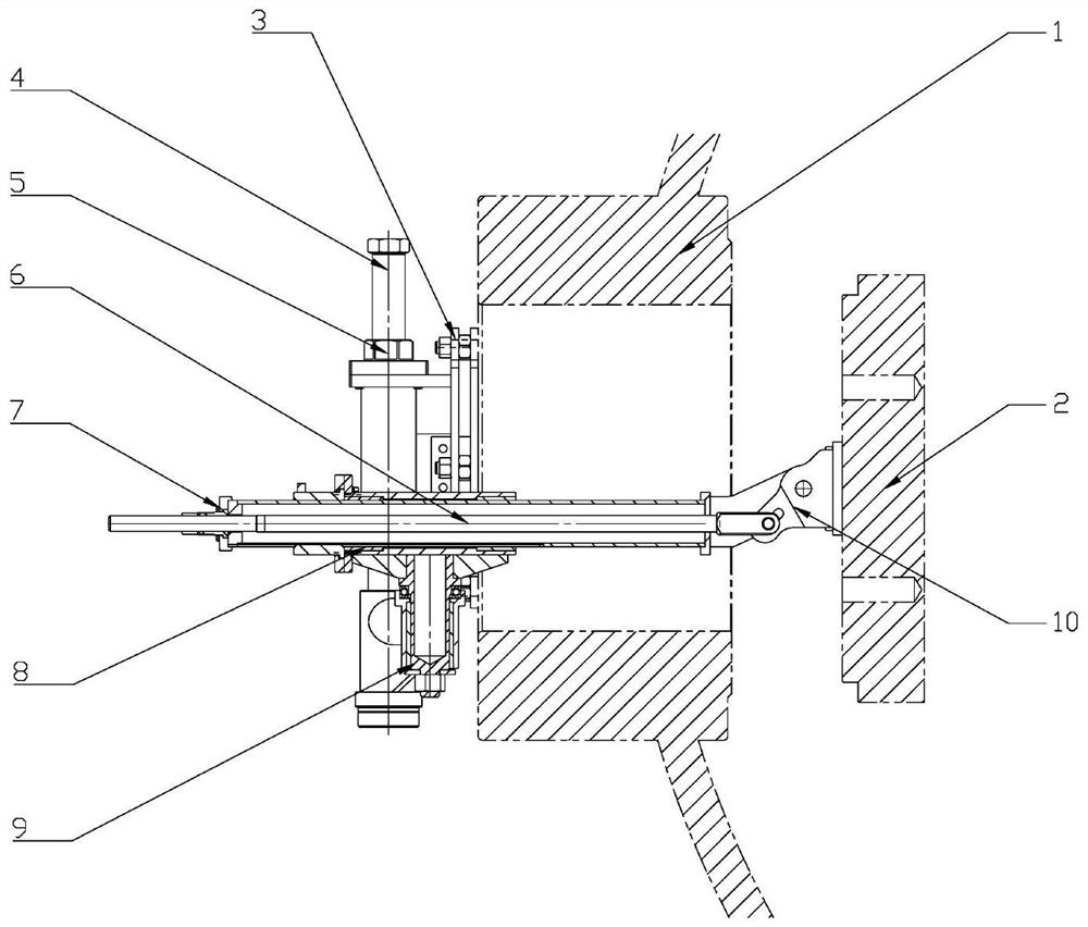
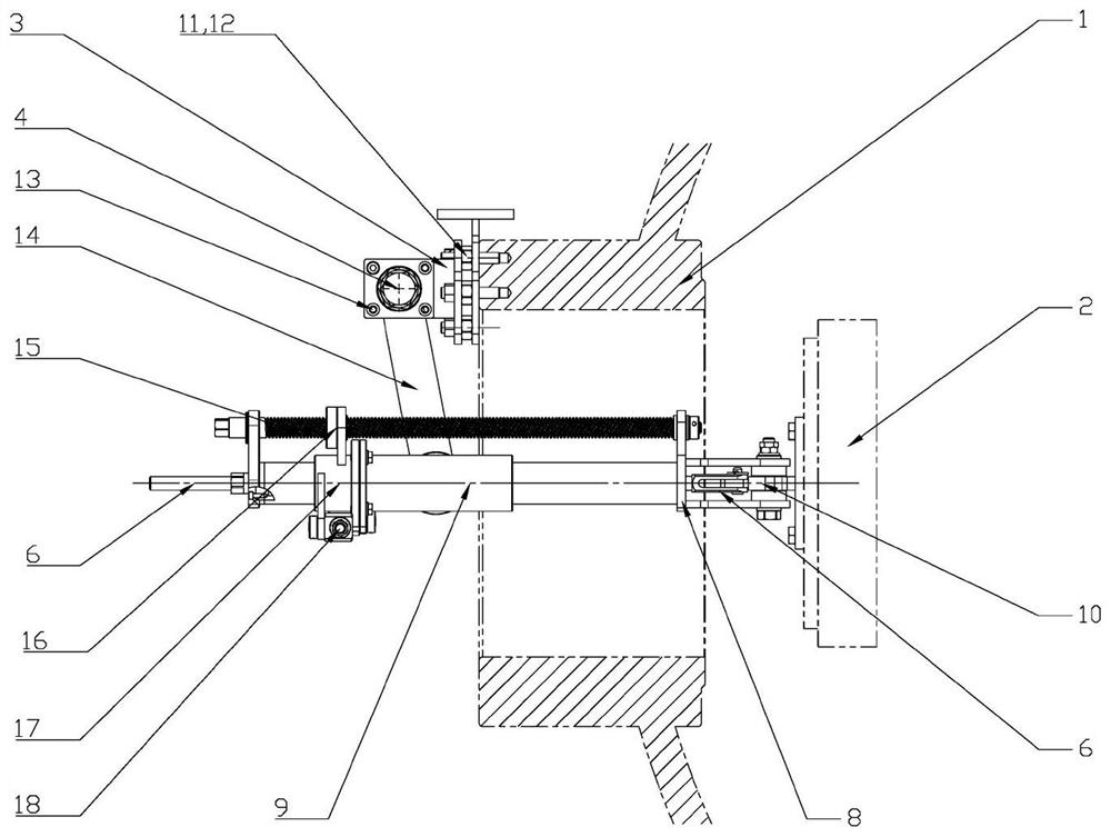
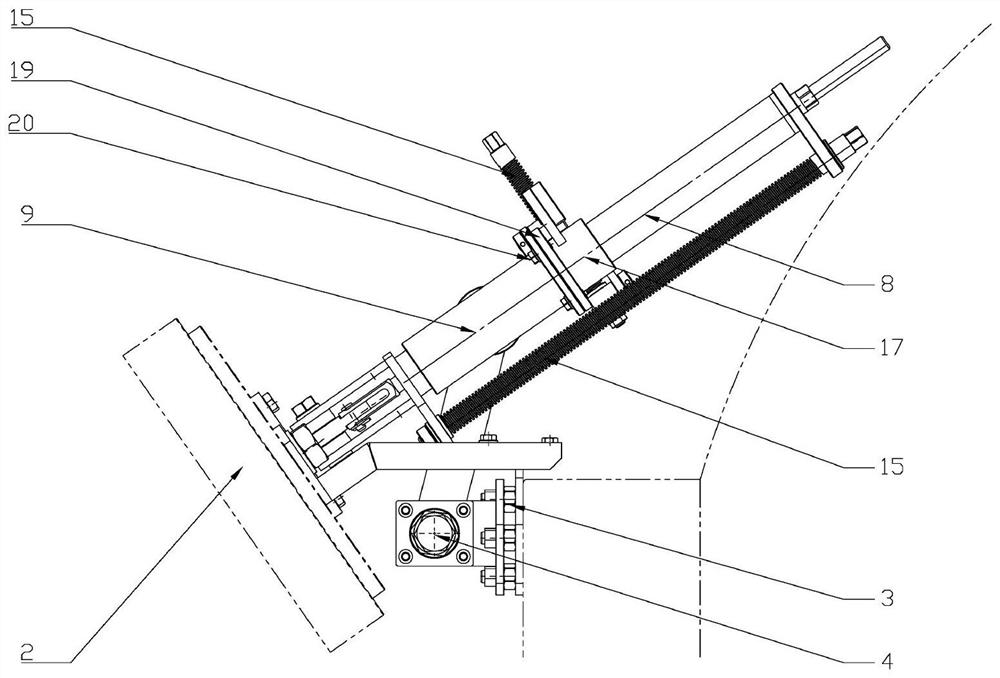
[0027] Such as Figure 1-5 As shown, the invention provides a self-sealing manhole cover removal tool for power station container equipment, which can realize the movement, rotation, flip and position adjustment of the manhole cover, including the manhole flange mounting seat 3, the lifting screw 4. Lifting screw nut 5, flip screw nut 6, flip screw nut 7, support tube 8, sliding support seat 9, manhole cover mounting seat 10,

[0028] The manhole flange mounting seat 3 is fixed on the high pressure heater manhole flange 1 through stud bolts 11 and nuts 12, the lifting screw 4 is installed in the sleeve of the manhole flange mounting seat 3, the lifting screw nut 5 and the lifting screw 4 pass through Threaded conn...


PUM


Abstract

The invention belongs to the technical field of mechanical design and particularly relates to a self-sealing manhole cover plate dismounting tool for power station container equipment The self-sealingmanhole cover plate dismounting tool comprises manhole flange mounting bases, a lifting lead screw, an overturning lead screw, a supporting pipe, a sliding supporting base and a manhole cover plate mounting base; the manhole flange mounting bases are fixed to a high-pressure heater manhole flange; the lifting lead screw is mounted in a sleeve of the manhole flange mounting base; the lifting leadscrew is used for adjusting the positions of a tool and a manhole cover plate in the vertical direction; the supporting pipe is mounted in a horizontal sleeve of the sliding supporting base; the overturning lead screw is mounted in the supporting pipe; the bottom end of the supporting pipe and the bottom end of the overturning lead screw are fixed into two holes of the manhole cover plate mountingbase through bolts respectively; and the manhole cover plate mounting base is fixed to the manhole cover plate through screws. According to the self-sealing manhole cover plate dismounting tool for the power station container equipment, the field work efficiency can be improved, and the safety risk of the operation industry is reduced.

Description

technical field [0001] The invention belongs to the technical field of mechanical design, and in particular relates to a tool for disassembling and assembling self-sealing manhole cover plates of container equipment in power stations. Background technique [0002] Each unit of Tianwan NPP Phase III has 4 high-pressure heaters. The manhole cover of the equipment adopts a self-sealing type, and the sealing performance is improved compared with the traditional sealing structure. However, the disassembly process of the manhole cover is more difficult: The manhole cover is elliptical. The disassembly process includes four steps: pushing in the manhole cover, turning vertically, rotating horizontally and pulling out. The vertical turning and horizontal rotation of the manhole cover are all in the water chamber of the high pressure heater , the size of the manhole cover is 550mm in the long axis, 470mm in the short axis, and weighs about 105Kg, and the inside of the water chamber i...

Claims


Application Information

Patent Timeline
Patent Type & Authority Applications(China)
IPC IPC(8): B25B27/00
CPCB25B27/00
Inventor 任苹吴军唐俊杰孟余兵陈红刘思宇徐钰涞李洪晨杨正笛高恒张晓蒙
Owner JIANGSU NUCLEAR POWER CORP
Why Eureka
Try Eureka