
A precision mold injection molding separation equipment

A technology for separation equipment and precision molds, which is applied in the field of separation equipment for injection molded parts of precision molds. It can solve the problems that the shearing mechanism cannot shear, increase the scrap rate, and low separation efficiency, so as to achieve good market application value and improve product qualification. The effect of high efficiency and high degree of automation

Active Publication Date: 2021-07-13
深圳市豪华科技有限公司
View PDF11 Cites 0 Cited by
  • Summary
  • Abstract
  • Description
  • Claims
  • Application Information

AI Technical Summary

Problems solved by technology

[0002] In the production of injection molded parts, production modes such as one mold with two cavities and one mold with four cavities are often used. Taking one mold with four cavities as an example, four pieces are produced at the same time after injection molding with a mold with four cavities. Injection molded parts, during the injection process, the liquid resin flows in from the mold inlet, then flows through the flow channel set in the mold, and then divides the liquid into the four product cavities at the end. After the injected resin cools down, four connected injection molded parts are obtained. The common connection between the four injection molded parts is called the runner, and the connection position between the injection molded part and the runner is called the gate. In order to obtain a single product, after the injection molding machine opens the mold, the injection molded part must be separated from the mold and the single product and the mold must be separated. The runner is disconnected from the gate, and the separation and disconnection work is often done manually, which consumes a lot of manpower, resulting in an increase in production costs and a decrease in production efficiency, or the injection molded parts are cut at the gate by an automatic punching structure. Splitting by shearing, because this separation method directly exerts a large external force on the injection molded parts, it is easy to cause deformation of the injection molded parts, increase the scrap rate, and also increase the production cost, and a single shearing mechanism cannot simultaneously The gate is sheared, the separation efficiency is low, and some equipment does not set up a collection box for collecting waste after separating the injection molded parts, which pollutes the working environment

Method used


Image

  • A precision mold injection molding separation equipment
  • A precision mold injection molding separation equipment
  • A precision mold injection molding separation equipment

Examples


Embodiment Construction

[0027] In order to facilitate the understanding of the present invention, the present invention will be described in more detail below in conjunction with the accompanying drawings and specific embodiments. Preferred embodiments of the invention are shown in the accompanying drawings. However, the present invention can be implemented in many different forms and is not limited to the embodiments described in this specification. On the contrary, these embodiments are provided to make the understanding of the disclosure of the present invention more thorough and comprehensive.

[0028] It should be noted that when an element is referred to as being “fixed” to another element, it can be directly on the other element or there can also be an intervening element. When an element is referred to as being "connected to" another element, it can be directly connected to the other element or intervening elements may also be present. The terms "fixed", "integrated", "left", "right" and si...


PUM


Abstract

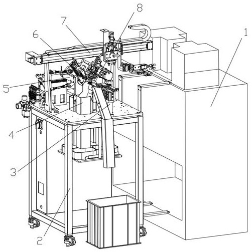
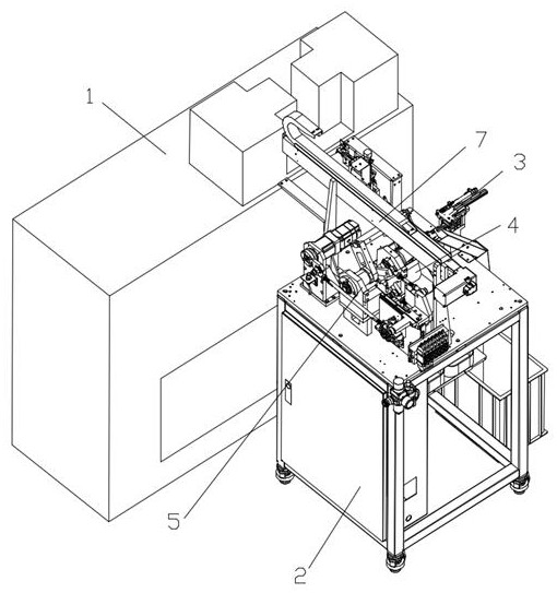
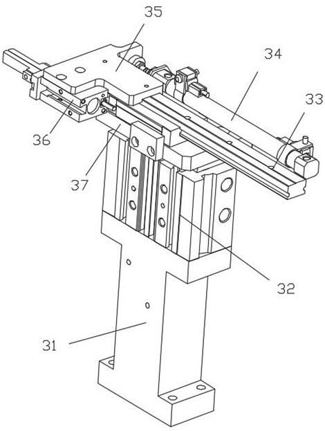
The invention relates to a precision mold injection molding separation equipment, which includes an injection molding machine. A workbench is arranged on the left side of the injection molding machine. A cylinder fixing seat is installed in the middle of the upper surface of the workbench. One finger cylinder, the working end of the first finger cylinder is fixed with jaws for placing injection molded parts, and the working end of the first finger cylinder is set upwards, the rear side of the cylinder fixing seat is provided with a rotary pick-up device, and the rotary pick-up device The parts device takes out the injection molded parts from the injection molding machine and puts them on the jaws. The left and right sides of the cylinder holder are respectively provided with a receiving assembly 1 and a collection assembly 2 for collecting injection molded parts. The front of the cylinder holder The side is provided with a material receiving assembly 3 for collecting injection molded parts, and the rear side of the rotary pick-up device is provided with an injection molded parts separation mechanism; the invention has a high degree of automation, improves the product qualification rate, saves costs, and improves work efficiency , has good market application value.

Description

technical field [0001] The invention relates to the technical field of connector pins and testing, in particular to a precision mold injection molding separation device. Background technique [0002] In the production of injection molded parts, production modes such as one mold with two cavities and one mold with four cavities are often used. Taking one mold with four cavities as an example, four pieces are produced at the same time after injection molding with a mold with four cavities. Injection molded parts, during the injection process, the liquid resin flows in from the mold inlet, then flows through the flow channel set in the mold, and then divides the liquid into the four product cavities at the end. After the injected resin cools down, four connected injection molded parts are obtained. The common connection between the four injection molded parts is called the runner, and the connection position between the injection molded part and the runner is called the gate. I...

Claims


Application Information

Patent Timeline
Patent Type & Authority Patents(China)
IPC IPC(8): B29C45/38B29C45/42
CPCB29C45/382B29C45/4225
Inventor 李仕可
Owner 深圳市豪华科技有限公司
Learn More