Mounting method of instrument board cross beam mounting plates and instrument board cross beam mounting plates

An installation method and instrument panel technology, applied in transportation and packaging, connection between superstructure subassemblies, superstructure subassemblies, etc., can solve problems such as poor position accuracy, improve position accuracy and reduce welding The effect of tolerance and relative position accuracy

Pending Publication Date: 2021-03-19
QOROS
View PDF11 Cites 0 Cited by
  • Summary
  • Abstract
  • Description
  • Claims
  • Application Information

AI Technical Summary

Problems solved by technology

[0004] The technical problem to be solved by the present invention is to provide an installation method and an instrument panel beam mounting plate installation method to overcome the defect of poor position accuracy of the instrument panel beam mounting plate due to multiple welding of the vehicle front cabin assembly in the prior art. plate beam mounting plate

Method used


Image

  • Mounting method of instrument board cross beam mounting plates and instrument board cross beam mounting plates
  • Mounting method of instrument board cross beam mounting plates and instrument board cross beam mounting plates
  • Mounting method of instrument board cross beam mounting plates and instrument board cross beam mounting plates

Examples


Embodiment Construction

[0042] Various embodiments of the invention will be described with reference to the accompanying drawings. In the drawings of the specification, elements having similar structures or functions will be denoted by the same element symbols. It can be understood that the drawings are only for the purpose of illustrating various embodiments of the present invention, and are not intended to describe the present invention exhaustively, nor limit the scope of the present invention.

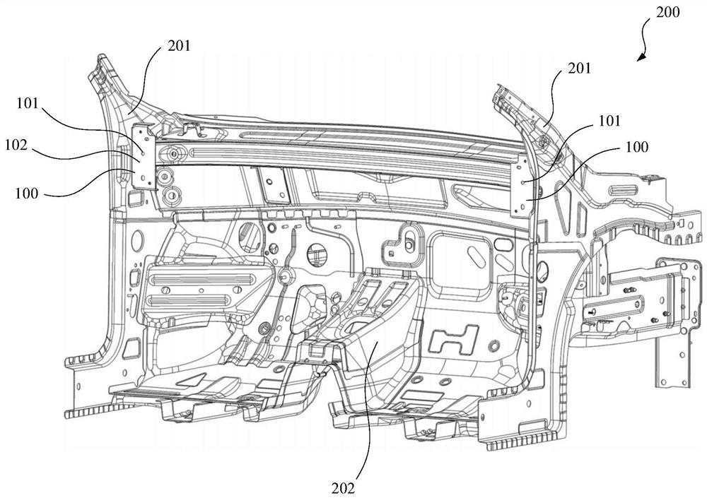
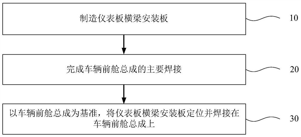
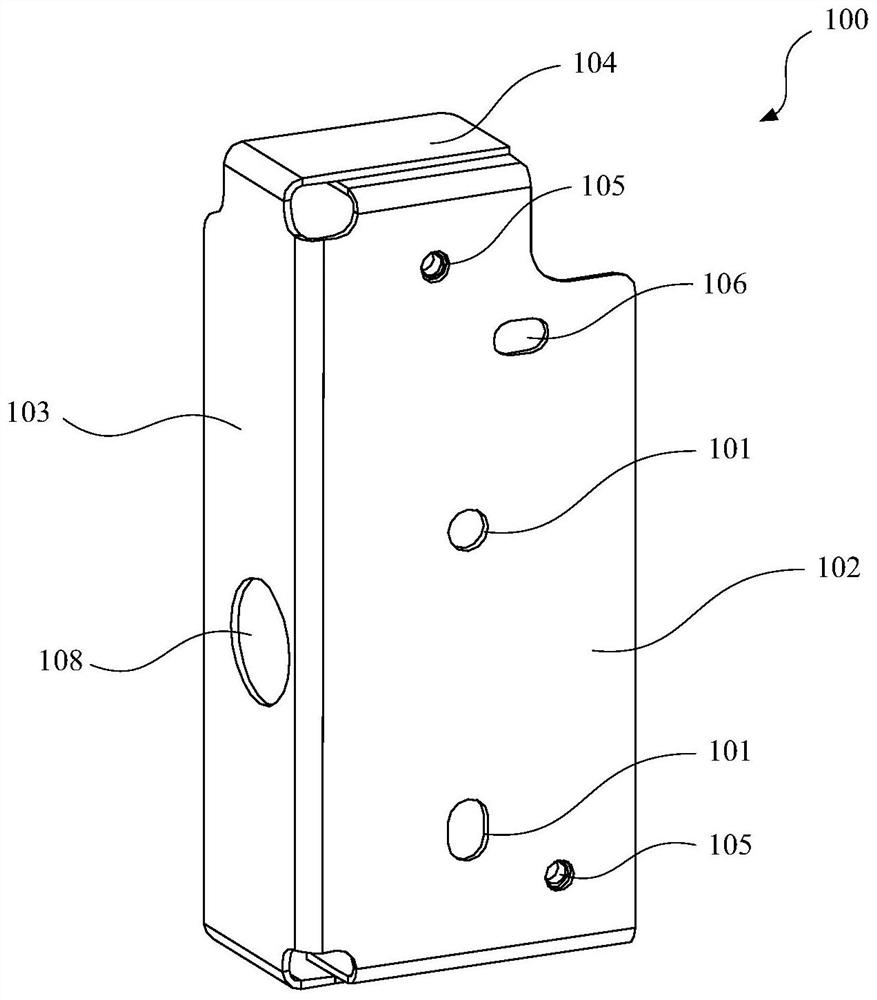
[0043] The present invention provides a method for installing an instrument panel beam installation plate 100 . Such as figure 1 As shown, it is used to weld the left and right instrument panel cross beam mounting plates 100 to the corresponding A-pillar upper inner panel 201 of the vehicle front compartment assembly 200 to form an instrument panel cross beam ( not shown in the figure) installed interface. Such as figure 2 As shown, the installation method includes the following steps:

[0044] Step...


PUM


Abstract

The invention discloses a mounting method of instrument board cross beam mounting plates and the instrument board cross beam mounting plates. The mounting method comprises the following steps that: S1, the instrument board cross beam mounting plates are manufactured; S2, main welding of a vehicle front cabin assembly is completed; and S3, with the vehicle front cabin assembly as the benchmark, theinstrument board cross beam mounting plates are positioned and welded to the vehicle front cabin assembly. According to the mounting method of the instrument board cross beam mounting plates, after main welding of the vehicle front cabin assembly is completed, the instrument board cross beam mounting plates are welded and mounted on the vehicle front cabin assembly, and through backward performing of the welding step of the instrument board cross beam mounting plates, the welding tolerance accumulation of the instrument board cross beam mounting plates in the welding process of the vehicle front cabin assembly is reduced as much as possible, the position precision of the left instrument board cross beam mounting plate and the right instrument board cross beam mounting plate is effectivelyimproved, then the mounting precision of the instrument board cross beam is improved in the subsequent process, and the accuracy of the relative position of the instrument board cross beam and the vehicle front cabin assembly is guaranteed.

Description

technical field [0001] The invention relates to the field of automobile manufacturing, in particular to a method for installing an instrument panel beam mounting plate and the instrument panel beam mounting plate. Background technique [0002] At present, the instrument panel beam and the vehicle front compartment assembly are connected by means of the instrument panel beam mounting plate. First, the left and right instrument panel beam mounting plates are respectively welded to the corresponding upper inner panel of the A-pillar, and then the A-pillar The combination of the upper inner panel and the instrument panel beam mounting plate is welded with the vehicle front compartment assembly and other components in the form of components to form a complete vehicle front compartment assembly structure. [0003] During this process, the front cabin assembly of the vehicle needs to be welded many times, and the positioning error generated by each welding will continue to accumula...

Claims


Application Information

Patent Timeline
Patent Type & Authority Applications(China)
IPC IPC(8): B62D25/08B62D25/14B62D27/02
CPCB62D25/08B62D25/145B62D27/02
Inventor 于鹏锡
Owner QOROS
Why Eureka
Try Eureka