Method for testing strength of upper support of shock absorber and shock absorber
A technology for strength testing and shock absorbers, which is applied in the field of shock absorbers and automobile shock absorbers, can solve problems such as inaccurate test data and inconsistency in the way of force, so as to improve test efficiency, shorten test time, and reduce test times Effect
- Summary
- Abstract
- Description
- Claims
- Application Information
AI Technical Summary
Problems solved by technology
Method used
Image
Examples
Embodiment 1
[0032] The technical solutions in this embodiment will be clearly and completely described below in conjunction with the accompanying drawings in this embodiment, but this should not be construed as limiting the present invention to a specific embodiment, but only for explanation and understanding:
[0033] The whole vehicle is a complete body consistent with the real vehicle, including the body and four wheels. The shock absorber is installed between the body and the wheels of the vehicle, and the shock absorber includes a piston rod 2 and an upper support 3 .
[0034] This embodiment provides a method for testing the strength of a support on a shock absorber,
[0035] Include the following steps:
[0036] Step S1: Establish a vehicle cratering model, simulate the cratering process of the whole vehicle, and obtain the maximum bearing force F of the piston rod 2 max , and determine the vehicle speed v based on the maximum bearing force of the piston rod 2 max .
[0037] Thr...
Embodiment 2
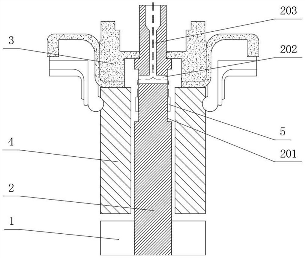
[0052] like figure 1 As shown, this embodiment provides a shock absorber for measuring the force on the piston rod 2, and the shock absorber is improved to facilitate the use of Embodiment 1.
[0053] The shock absorber includes a shock absorber, a piston rod 2 and an upper support 3 . The damping cylinder and the upper support 3 are sleeved on both ends of the piston rod 2 respectively, and a buffer sleeve 4 is provided between the damping cylinder and the upper support 3 .
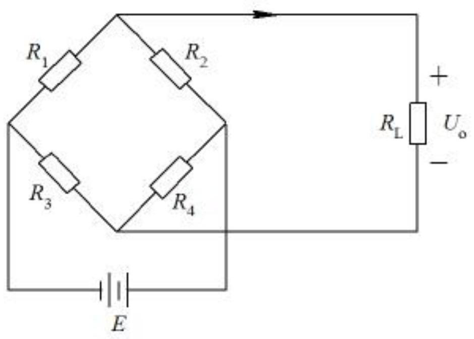
[0054] One end of the piston rod 2 close to the upper support 3 sets has an opposite first side and a second side, and the first side and the second side are processed with avoidance grooves 201, and the avoidance grooves 201 on the first side and the second side are bottomed Both are provided with strain gauges 5 , that is, the strain gauges 5 are arranged at 0° and 180° of the circumferential surface of the piston rod 2 . Bottoms of the two avoidance grooves 201 are processed with embedding holes 202...
PUM
 Abstract
Description
Claims
Application Information
 - R&D
- Intellectual Property
- Life Sciences
- Materials
- Tech Scout
- Unparalleled Data Quality
- Higher Quality Content
- 60% Fewer Hallucinations
Browse by: Latest US Patents, China's latest patents, Technical Efficacy Thesaurus, Application Domain, Technology Topic, Popular Technical Reports.
© 2025 PatSnap. All rights reserved.Legal|Privacy policy|Modern Slavery Act Transparency Statement|Sitemap|About US| Contact US: help@patsnap.com


